G0645 Benchtop Mortising Machine
-15-
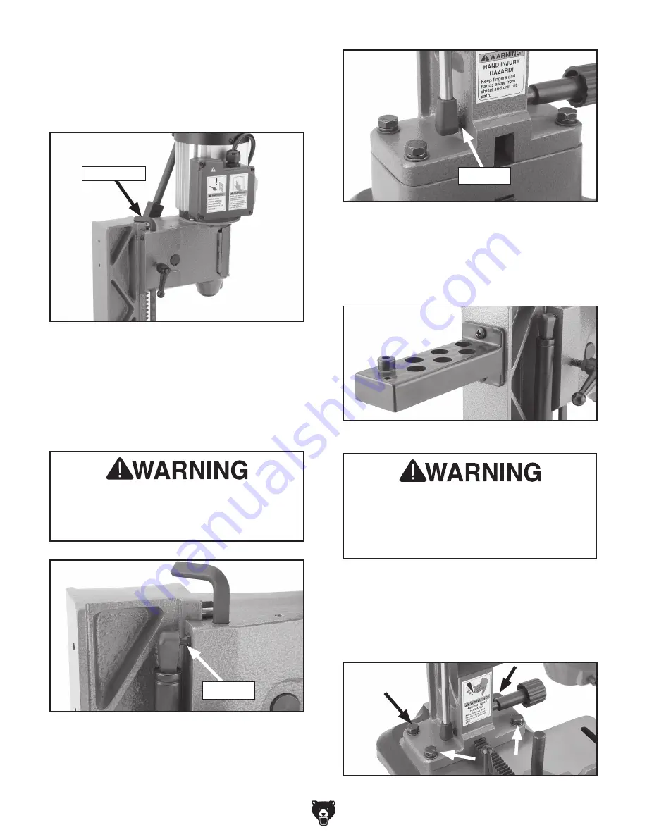
Figure 13
. Tool storage rack installed.
5.
Install the tool storage rack, as shown in
Figure 13
, with the M6-1 x 15 Phillips head
screws already attached to the headstock.
Figure 12
. Gas spring attached to bottom of
column.
Depth Stop
The headstock must be locked in place
before the gas spring is installed. Serious
personal injury can occur if the headstock
drops during installation.
3.
Lift the headstock to the top position using
the hand lever. Position the depth stop so it
contacts the top of the headstock, as shown
in
Figure 10
, and secure the lock knob so the
headstock does not move.
Figure 10
. Depth stop contacting headstock.
Ball Stud
Figure 11
. Gas spring attached to top of
headstock.
4.
Snap the gas spring ball sockets onto the ball
studs, as shown in
Figures 11 & 12
.
Tip
:
It may help to use a flat head screwdriver
to leverage the bottom gas spring ball socket
onto the ball stud.
Ball Stud
6.
Remove the four M8-1.25 x 25 hex bolts,
flat washers and lock washers securing the
column to the base, shown in
Figure 14
, and
temporarily lay the headstock on its side on
the workbench.
Figure 14
. Hex bolts and washers securing
column to base.
CRUSHING HAZARD!
Have an assistant hold the headstock during
the following step. The headstock is heavy
and could cause serious personal injury if
not supported.
Summary of Contents for G0645
Page 2: ... ...
Page 5: ...G0645 Benchtop Mortising Machine 3 Machine Data Sheet ...
Page 6: ... 4 G0645 Benchtop Mortising Machine ...
Page 8: ... 6 G0645 Benchtop Mortising Machine Safety Instructions for Machinery ...
Page 9: ...G0645 Benchtop Mortising Machine 7 ...
Page 14: ... 12 G0645 Benchtop Mortising Machine Hardware Recognition Chart ...
Page 32: ......
Page 33: ... ...
Page 34: ... ...
Page 36: ... ...


