Grizzly G0555L Owner'S Manual Download Page 21

G0555LX


(Mfg. Since 3/13)

-19-

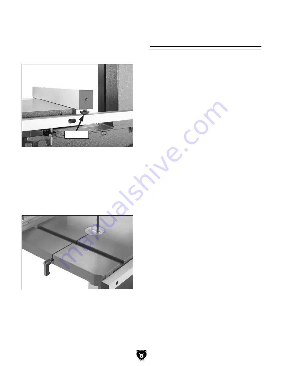
17.  install the table insert and table pin, as show 

in 

figure 20.


important: Make sure you re-install the table 
pin. This pin keeps the table surfaces on 
either side of the slot even with the chang-
es in operating pressures and temperature 
changes.

figure 20. table pin and insert installed.

figure 19. Fence rail pad installed.

rail pad

16.  thread the M6-1 hex nut onto the fence rail 

pad, then thread it into the rear underside of 
the fence (see 

figure 19) so that the fence 

rests the same height above the table along 
its full length. tighten the hex nut against the 
fence to secure the setting.

adjustment 

overview

the bandsaw is one of the most versatile wood-
working machines. as such it has multiple compo-
nents that must be properly adjusted for the best 
cutting results. 

For  safety  reasons  some  adjustments  and  test 
operations must be performed before performing 
other  necessary  adjustments.  below  is  an  over-
view of all the adjustments and the order in which 
they should be performed.

adjustment procedures include:

•  blade tracking
•  dust Collection
•  power Connection
•  test run
•  tension blade
•  adjusting blade support bearings
•  adjusting blade guide bearings
•  table tilt Calibration
•  aligning table
•  aligning Fence

Summary of Contents for G0555L

Page 1: ...april 2013 ts Warning No portion of this manual may be reproduced in any shape Or form without the written approval of Grizzly Industrial inc KN14662 printed in TAIWAN MODEL G0555LX 14 DELUXE BANDSAW...

Page 2: ...g grinding tool integrity and the usage of personal protective equipment The manufacturer will not be held liable for injury or property damage from negligence improper training machine modifications...

Page 3: ...ble 28 Aligning Fence 29 SECTION 4 OPERATIONS 30 Operation Overview 30 Straight Cuts 31 Irregular Cuts 31 Basic Cutting Tips 31 Disabling Locking Switch 31 Workpiece Inspection 32 Guide Post 32 Table...

Page 4: ...specifications drawings and photographs of the machine we used when writing this manual However sometimes we still make an occasional mistake Also owing to our policy of continuous improve ment your...

Page 5: ...t bearings d Adjust upper guide to just clear workpiece e Hold workpiece firmly against table Figure 1 G0555LX identification Fence Miter Gauge Motor Blade Tension Scale Table Tilt Lock Knob Lower Bla...

Page 6: ...t Machine Weight 204 lbs Length x Width x Height 45 x 22 x 18 in Must Ship Upright N A Carton 2 Type Cardboard Box Content Stand Weight 42 lbs Length x Width x Height 0 x 0 x 0 in Must Ship Upright N...

Page 7: ...es Table Information Table Length 14 in Table Width 14 in Table Thickness 1 1 2 in Table Tilt Left 10 Right 45 deg Table Tilt Adjustment Type Manual Floor to Table Height 43 in Fence Locking Position...

Page 8: ...DANGEROUS ENVIRONMENTS Do not use machinery in areas that are wet cluttered or have poor lighting Operating machinery in these areas greatly increases the risk of accidents and injury MENTAL ALERTNES...

Page 9: ...g parts or flying debris Make sure they are properly installed undamaged and working correctly FORCING MAChINERY Do not force machine It will do the job safer and better at the rate for which it was d...

Page 10: ...DO NOT twist or put excessive stress on the blade while backing the work away LEAVING WORK AREA Never leave a machine running unattended Allow the bandsaw to come to a complete stop and use the padloc...

Page 11: ...peration and make sure it is connected to a power supply circuit that meets the requirements in the following section For your own safety and protection of property consult an electrician if you are u...

Page 12: ...Typical 6 15 plug and receptacle Grounding Prong Current Carrying Prongs 6 15 PLUG GROUNDED 6 15 RECEPTACLE Serious injury could occur if you connect the machine to power before completing the setup...

Page 13: ...for the new voltage and install ing a new plug according to the manufacturer s instructions Note If the diagram included on the motor con flicts with the one in this manual the motor may have changed...

Page 14: ...t 13mm 2 Needed for Setup Your machine was carefully packaged for safe transportation Remove the packaging materials from around your machine and inspect it If you discover the machine is damaged plea...

Page 15: ...2 x 3 8 x 6 TPI 1 C Bandsaw Body 2 D Trunnion Base 1 E Front Fence Rail 1 F Rear Fence Rail 1 G Miter Gauge Assembly 1 H Fence Assembly 1 I Trunnion Lock Knobs 2 J Upper Stand Braces 2 K Stand Top 1 L...

Page 16: ...es disposable gloves Plastic paint scraper optional Basic steps for removing rust preventative 1 Put on safety glasses 2 Coat the rust preventative with a liberal amount of cleaner degreaser then let...

Page 17: ...ent The physical environment where the machine is operated is important for safe operation and lon gevity of machine components For best results operate this machine in a dry environment that is free...

Page 18: ...lower stand braces attached to the stand side Upper Stand Brace Stand Side Lower Stand Brace x 8 2 Attach the remaining stand side to the assem bly as shown in Figure 9 with 8 1 4 20 x 5 8 hex bolts...

Page 19: ...against the stand assembly so they will not move Figure 12 Leveling the stand 7 With the help of other people lift the bandsaw assembly onto the stand and align the mount ing holes Have one person ho...

Page 20: ...unting holes in the trunnion base as shown in Figure 15 12 Secure the table by fully threading the two trunnion lock knobs onto the table bolts Figure 15 Installing the table onto the trunnion base Fi...

Page 21: ...t above the table along its full length Tighten the hex nut against the fence to secure the setting Adjustment Overview The bandsaw is one of the most versatile wood working machines As such it has mu...

Page 22: ...tracks Bandsaw wheels are either flat or crowned and both shapes track differently The G0555LX has crowned wheels As the wheels spin the blade naturally tracks to the highest point of the crown at th...

Page 23: ...th one hand and slowly adjust the tracking knob with the other hand until the blade consistently tracks in the center of the wheel 9 Tighten the wing nut to secure the setting then spin the upper whee...

Page 24: ...necting Power Figure 27 Disconnecting power 1 Turn the machine power switch OFF 2 Grasp the molded plug and pull it completely out of the receptacle Do not pull by the cord as this may damage the wire...

Page 25: ...ON button to test the disabling fea ture on the switch If the machine does not start the switch disabling feature is working as designed If the machine does start immediately stop it The switch disabl...

Page 26: ...detailed instructions Note Tensioning the blade according to the blade tension scale before the Test Run was an approximate tension The following procedures fine tunes the blade tension 1 DISCONNECT B...

Page 27: ...assembly lock bolt see Figure 29 6 Loosen the cap screw see Figure 29 on the support bearing adjustment shaft 7 Use the knurled knob to position the support bearing approximately 0 016 away from the b...

Page 28: ...Blade on Page 23 Tool Needed Qty Hex Wrench 4mm 2 To adjust the upper and lower blade guides 1 DISCONNECT BANDSAW FROM POWER Figure 33 Blade guide bearing controls Cap Screw Knurled Knob Locking Cap...

Page 29: ...ation When properly adjusted the positive stop bolt enables the table to be quickly returned perpen dicular to the blade To tilt the table to the left the positive stop bolt see Figure 36 must be lowe...

Page 30: ...the pointer adjust the pointer to 0 then retighten the Phillips head screw Figure 38 Location of the table tilt scale Tilt Scale Pointer Aligning Table To ensure cutting accuracy the table must be al...

Page 31: ...acket flange bolts Flange Bolts 3 of 6 Aligning Fence To ensure accurate cutting when using the fence the face of the fence must be parallel to the table miter slot and thus to the side of the blade T...

Page 32: ...rec ommend that you read books review industry trade magazines or get formal training before beginning any projects Regardless of the content in this section Grizzly Industrial will not be held liable...

Page 33: ...se relief cuts when possible Misusing the saw or using incorrect tech niques e g twisting the workpiece incorrect feed rate etc is unsafe and results in poor cuts Disabling Locking Switch Figure 42 Sw...

Page 34: ...t have large loose knots or plan ahead to avoid cutting through them Wet or Green Stock Cutting wood with a moisture content over 20 causes unneces sary wear on the blades increases the risk of kickba...

Page 35: ...eeds of 1800 and 3100 FPM Speed changes are made by re positioning the V belt in different pulley grooves Keep in mind cutting results are not just related to blade speed Other factors include the typ...

Page 36: ...eration Blade Length Measured by the circumference blade lengths are usually unique to the brand of your bandsaw and the distance between wheels Blades will vary slightly even in the same length becau...

Page 37: ...ne pitch will cut slower but smoother while fewer teeth per inch coarse pitch will cut rougher but faster As a general rule choose blades that will have at least three teeth in the material at all tim...

Page 38: ...e then remove the table insert and table pin see Figure 50 1 DISCONNECT BANDSAW FROM POWER 2 Move the blade tension quick release lever to the left to release blade tension 3 Adjust the upper blade gu...

Page 39: ...utting with the grain of the wood stock For plywood and other processed wood ripping simply means cutting down the length of the workpiece Beveled rip cuts may be performed by tilting the table To mak...

Page 40: ...kpiece Figure 53 shows an example of a crosscutting operation Figure 53 Example of a crosscutting operation with the miter gauge Figure 54 Example of a resawing operation When resawing thin pieces a w...

Page 41: ...8 1 4 5 8 3 8 11 4 1 2 21 2 5 8 33 4 3 4 51 2 One of the benefits of a bandsaw is its ability to cut multiple copies of a particular shape by stack ing a number of workpieces together However before...

Page 42: ...931 2 3 16 10 Raker 0 025 G5156 931 2 3 16 14 Raker 0 025 G5157 931 2 1 4 4 Hook 0 025 G5158 931 2 1 4 6 Hook 0 025 G5159 931 2 1 4 10 Raker 0 025 G5160 931 2 1 4 14 Raker 0 025 G5161 931 2 1 4 18 Ra...

Page 43: ...aker RK blades are specifically designed for detail work in 1 and smaller kiln dried wood when a very clean finish is required They are also effective in plywood and other woods where tear out is a co...

Page 44: ...for a quick transition from a stationary base to full maneuverability G8984 Single Roller Stand G8985 5 Roller Stand These roller stands are invaluable when working solo in any shop for outfeeding and...

Page 45: ...tenance schedule Daily Check correct loose mounting bolts Check correct damaged saw blade Check correct worn or damaged wires Correct any other unsafe condition Monthly Check for V belt tension damage...

Page 46: ...3 V belt slipping 4 Motor connection is wired incorrectly 5 Plug receptacle is at fault 6 Motor bearings are at fault 7 Motor has overheated 8 Motor is at fault 9 Centrifugal switch is at fault 1 Use...

Page 47: ...rflow from dust collection system 1 Clean out dust port 2 Four options Check dust lines for leaks or clogs Move dust collector closer to saw Install a more powerful dust collector Use blast gates to i...

Page 48: ...Deflection is checked by push ing the V belt with moderate pressure as shown in Figure 64 and noting how much it moves If the V belt is not properly tensioned perform the following Tensioning V Belt p...

Page 49: ...emove the wheel from the shaft Make sure not to misplace the shaft key 8 Put new belt on 9 Align the wheel keyway with the shaft key and slide the wheel back onto the shaft 10 Secure the wheel with th...

Page 50: ...ocket 13mm 1 Wrench or Socket 19mm 1 Checking Wheel Alignment 1 DISCONNECT BANDSAW FROM POWER 2 Remove the table 3 With the blade on and properly tensioned hold a straightedge close to the center of b...

Page 51: ...to shim the wheel to be coplanar 3 With the straightedge touching both rims of the wheel that does not need to be adjusted measure the distance away from the other wheel with a fine ruler as shown in...

Page 52: ...teral wheel alignment viewed from above 7 Re tighten the hex nuts loosened in Step 6 Blade Lead Bandsaw blades may wander off the cut line when sawing as shown in Figure 74 This is called blade lead B...

Page 53: ...e out of the way and cut along the line halfway through the board Turn the bandsaw OFF and wait for the blade to stop Do not move the board 3 Clamp the board to the bandsaw table then slide the fence...

Page 54: ...NDSAW FROM POWER 2 Move the blade tension quick release lever to the left position to release blade tension Figure 76 3 Using two 14mm wrenches loosen the lower jam nuts and thread them up the shaft 4...

Page 55: ...at the time of printing but may not match your machine If you find this to be the case use the wiring diagram inside the motor junction box CAPACITORS INVERTERS Some capacitors and power inverters sto...

Page 56: ...54 G0555LX Mfg Since 3 13 READ ELECTRICAL SAFETY ON PAGE 53 Electrical Locations Figure 77 G0555LX ON OFF switch Motor Switch...

Page 57: ...ound Start Capacitor 300MFD 125VAC 110V Prewired Wiring Diagram Motor at 110V 120V prewired 3 RED 1 BLACK 2 GRAY 4 YELLOW O N O F F Neutral Hot Ground Ground Work Lamp 40 Watt Maximum Start Capacitor...

Page 58: ...AC G Ground Start Capacitor 300MFD 125VAC 220V Rewired Wiring Diagram Motor at 110V 120V prewired 3 RED 1 BLACK 2 GRAY 4 YELLOW O N O F F Neutral Hot Ground Ground Work Lamp 40 Watt Maximum Start Capa...

Page 59: ...4 75 76 79 80 190 191 81 82 83 84 85 86 88 89 92 93 94 95 113 115 116 117 118 119 120 121 122 123 124 127 128 129 131 133 134 135 214 138 139 140 141 154 155 162 167 168 212 170 1 58 49 50 66 62 16 43...

Page 60: ...2 66 P0555LX066 BLADE GUARD WASHER 10 14 P0555LX014 PUSH BUTTON SWITCH ASSY 68 P0555LX068 RIBBED V BELT 200J5 14 1 P0555LX014 1 SWITCH COVER 69 P0555LX069 LOWER WHEEL COVER HINGE 14 2 P0555LX014 2 SW...

Page 61: ...PSS12 SET SCREW 1 4 20 X 1 122 P0555LX122 ADJUST NUT 169 PN05 HEX NUT 1 4 20 123 PCAP01 CAP SCREW 1 4 20 X 5 8 170 P0555LX170 DOG PT SET SCR 5 16 18 X 1 2 124 P0555LX124 CORD CLAMP 3 8 173 P0555LX173...

Page 62: ...10 111 112 113 104 201 202 204 205 206 207 211 212 209 210 212 211 213 208 161 161 52 160 166 37 94 95 58 53 53 58 197 127 172 184 87 55 159 77 27 78 70 87 32 54 107 126 130 157 192 153 131 36 113 132...

Page 63: ...161 P0555LX161 REAR RAIL END CAP 99 PRP15M ROLL PIN 3 X 8 163 PFH19 FLAT HD SCR 1 4 20 X 3 8 100 P0555LX100 TABLE LOCK PIN 166 P0555LX166 FENCE SCALE 101 P0555LX101 TRUNNION 169 PN05 HEX NUT 1 4 20 1...

Page 64: ...1 TOUCH UP PAINT GRIZZLY GREEN 224 PLABEL 11A SAFETY GLASSES LABEL 219 P0555LX219 MODEL NUMBER LABEL 225 PLABEL 12A READ MANUAL LABEL 220 P0555LX220 GRIZZLY COM LABEL 215 216 216 217 217 218 219 220...

Page 65: ...metalworker ____ 0 2 Years ____ 2 8 Years ____ 8 20 Years ____20 Years 6 How many of your machines or tools are Grizzly ____ 0 2 ____ 3 5 ____ 6 9 ____10 7 Do you think your machine represents a good...

Page 66: ...LINE FOLD ALONG DOTTED LINE GRIZZLY INDUSTRIAL INC P O BOX 2069 BELLINGHAM WA 98227 2069 Place Stamp Here Name_______________________________ Street_______________________________ City______________S...

Page 67: ...tried in the State of Washington County of Whatcom We shall in no event be liable for death injuries to persons or property or for incidental contingent special or consequential damages arising from...

Page 68: ...Buy Direct and Save with Grizzly Trusted Proven and a Great Value Since 1983 ORDER 24 HOURS A DAY 1 800 523 4777 Visit Our Website Today For Current Specials...

Reviews: