Crathco
®
5000 Series Manual
Page 19
Annual Maintenance (cont.)
4.
Remove dasher assembly, inspect stator bearings and replace shaft seal set. (See Care and Cleaning).
5.
Remove rear panel and inspect "V" belt.
6.
Inspect the drive shaft square hole for wear (rounding-out).
7.
Check drive shaft and motor shaft bearings for excessive wear.
8.
Reinstall side and back panels.
9.
Re-connect power supply.
Belt Adjustment
Check the belt tension. The proper belt deflection is 1/2" overall. If the deflection is more than 1/2" the motor will
need to be lowered. If the deflection is less than 1/2" the motor will need to be raised. Follow this procedure to
adjust the motor to achieve proper belt tension.
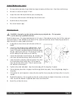
1)
Unplug the machine and remove both side and the rear
panels.
2)
Locate the motor flange bearings (#W038.0009). These
are the pillow block bearings that hold the motor to the
cradle. The motor is double shafted and the shaft extends
through a bearing on each end. The bearing is held to the
motor cradle by two allen bolts on each bearing.
3)
Loosen the allen bolts on each bearing. Do not loosen the
set screws that hold the bearing collar to the motor shaft.
4)
Lower the motor or raise the motor as needed. The motor
must be kept level from front to back. Do not lower or
raise only one end of the motor. This will result in exces-
sive belt wear and belt noise.
5)
Tighten all four allen bolts down. Align the motor pulley with the top pulley if needed.
6)
The motor pulley should be in alignment with the large (driven) top pulley. Use a straight edge along the
top pulley.
7)
If the pulleys are not in alignment, remove the setscrew from the motor pulley and move either in or out as
needed.
8)
Reinstall the setscrew. Use non-permanent loc-tite on the setscrew and tighten it back down on the motor
shaft. Be sure the setscrew is tightened down flat on the motor shaft.
9)
Return the unit back to service.
CAUTION: Unplug the machine before performing any adjustments. This procedure
must be done by a qualified technician.
Summary of Contents for Crathco 5311
Page 2: ......
Page 42: ...Page 42 Crathco 5000 Series Manual 5511 Electrical Components 5511 0102 057 3 20 00 ...
Page 44: ...Page 44 Crathco 5000 Series Manual 5311 Front Electrical Box CR CR CR CR ...
Page 45: ...Crathco 5000 Series Manual Page 45 5511 Front Electrical Box 5511 0101 057 3 20 00 ...
Page 53: ...Crathco 5000 Series Manual Page 53 5311 Spinner Hook Up with Timer Wiring Diagram ...
Page 58: ...Page 58 Crathco 5000 Series Manual 5311 Ladder Diagram 115V 60 Hz ...
Page 59: ...Crathco 5000 Series Manual Page 59 5511 Ladder Diagram 208 230V 50 Hz 5511 0103 057 3 20 00 ...
Page 68: ...Refrigeration Circuit Page 68 Crathco 5000 Series Manual ...
Page 70: ......
Page 71: ......


