

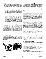


INLET
TUBE
END
PLUG
AIR HOLES
ARROWS
MUST FACE
INTO AIR FLOW
AIR FLOW DIRECTION
FLANGE
Figure 4. Air duct detector inlet sampling tube:
A78-2047-00
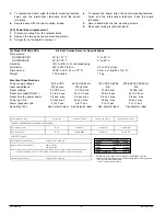
Figure 5. Tube mounting configurations with
varying air flow direction:
AIR FLOW
DIRECTION
DETECTOR
HOUSING
DOTS INDICATE POSITION OF
SAMPLING TUBE HOLES
AIR FLOW
DIRECTION
DETECTOR
HOUSING
INLET
TUBE
EXHAUST
TUBE
AIR FLOW
DIRECTION
EXHAUST
TUBE
INLET
TUBE
INLET
TUBE
EXHAUST
TUBE
DETECTOR
HOUSING
AIR FLOW
DIRECTION
EXHAUST
TUBE
INLET
TUBE
DETECTOR
HOUSING
A.
B.
C.
D.
NOTE: Orientations C and D apply ONLY to metal sampling tubes.
HORIZONTAL MOUNTING OF HOUSING
VERTICAL MOUNTING OF HOUSING
WARNING
In no case should more than 2 air inlet holes be cut off the
tube. There must be a minimum of 10 holes in the tube ex-
posed to the air stream.
[5.4.2] Installation For Ducts More Than 8
Feet Wide
NOTE: To install inlet tubes in ducts more than 8 feet wide,
work must be performed inside the air duct. Sampling of
air in ducts wider than 8 feet is accomplished by using
the ST-10 inlet sampling tube. If the tube is shorter than
the width of the air duct, install the end plug into the inlet
tube as shown in Figure 4 and support the end opposite
the duct smoke detector.
Install the inlet tube as follows:
1. Drill a
3
/
4
” inch hole in the duct directly opposite the hole
already drilled for the inlet tube. Make sure the hole is 1 to
2”below the inlet hole on the opposite side of the duct to
allow for moisture drainage.
2. Slide the inlet tube with the flange into the housing bush-
ing that meets the air flow first. Position the tube so that
the arrows point into the air flow. Secure the tube flange
to the housing bushing with two #6 self-tapping screws.
3. From inside the duct, couple the other sections of the in-
let tube to the section already installed using the
1
/
2
-inch
conduit fittings supplied. Make sure that the holes on
both of the air inlet tubes are lined up and facing into the
A78-2045-00
[5.4] Sampling Tube Installation for Ducts Greater
Than 1
1
/
2
Feet Wide
The sampling tube is identified by a series of air inlet holes
on the tube. A telescoping tube is included for ducts up to
18” in width. All other lengths must be purchased sepa-
rately. Order the correct length, as specified in Table 1, for
width of the duct where it will be installed. The exhaust tube
is molded onto the base of the duct housing, and the A2440-
00 Exhaust Tube Extension is available as an accessory in
those cases where the molded exhaust port does not ex-
tend at least 2 inches into the duct.
The inlet tube is always installed with the air inlet holes fac-
ing into the air flow. To assist proper installation, the tube’s
mounting flange is marked with arrows. Make sure the inlet
tube is mounted so that the arrows point into the air flow
(see Figure 4). Figure 5 shows the various combinations of
tube mounting configurations with respect to air flow. Mount-
ing the detector housing in a vertical orientation is accept-
able, provided that the air flows directly into the sampling
tube holes as indicated in Figure 4.
Table 1. Inlet tubes required for different duct
widths:
Outside Duct Width
Inlet Tube Required
1 to 2 ft.
ST-1.5
2 to 4 ft.
ST-3
4 to 8 ft.
ST-5
8 to 12 ft.
ST-10
[5.4.1] Installation For Ducts Greater Than 1
1
/
2
Feet But Less Than 8 Feet Wide
1.
If the tube is longer than the width of the air duct, drill a
3
/
4
”
hole in the duct opposite the hole already cut for the inlet
tube. Make sure the hole is 1” to 2” below the inlet hole on
the opposite side of the duct to allow moisture drainage
away from the detector.
If the tube is shorter than the width
of the air duct, install the end plug into the inlet tube as
shown in Figure 4. Sampling tubes over 3 ft. long must be
supported at the end opposite the duct detector.
2. Slide the tube into the housing bushing that meets the air
flow first. Position the tube so that the arrows point into
the air flow.
3. Secure the tube flange to the housing bushing with two
#6 self-tapping screws.
4. For tubes longer than the width of the air duct, the tube
should extend out of the opposite side of the duct. If there
are more than 2 holes in the section of the tube extending
out of the duct, select a different length using Table 1.
Otherwise, trim the end of the tube protruding through the
duct so that 1” to 2” of the tube extend outside the duct.
Plug this end with the end plug and tape closed any holes
in the protruding section of the tube. Be sure to seal the
duct where the tube protrudes.
D100-68-00
3
I56-1525-000


