Greystone CMD5B5 Series Installation Instructions Manual Download Page 6

Page  6

Relay 2

Direct

Relay 2

Test OFF

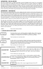
Use the <ROLL> key to toggle the available options. Relay 2 

operation may be set to Direct or Reverse. Direct operation 

means the relay is normally not energized and will energize on 

an alarm condition (the NO/NC PCB designations are correct). 

Reverse operation means the relay is normally energized 

and will de-energize on an alarm condition (the NO/NC PCB 

designations are reverse). Reverse operation can be used for 

"Fail Safe" operation as the relay will change state on power loss. 

Press <SAVE> to save the setting.

Use the <ROLL> key to toggle relay 2 ON or OFF.

<MENU> 

Press to advance to next menu item

<MENU> 

Press to advance to next menu item

14. DIRECT

15. TEST

TestMode

Disable

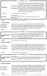
Use the <ROLL> key to enable or disable the Test mode. When disabled, the 

TEST switch or TEST input will not initiate the test function. When enabled, the 

TEST switch will initiate the test function. Note that the test mode will only 

function if the device is operating in the Normal mode, the test function cannot 

be initiated if any alarm is present. Press <SAVE> to save the setting.

<MENU> 

Press to advance to next menu item

16. TEST MODE

Only if 

Test Mode

 enabled

TestMode

Time 5

Fault Md

Disable

Use the <ROLL> key to scroll through the available options. 

The test mode operating time may be set from 1 to 15 

minutes in 1 minute increments. Press <SAVE> to save the 

setting. This item sets how long the test mode will operate 

when the TEST switch is pressed.

Use the <ROLL> key to enable, disable, or reset. When disabled, the device will 

not sound the buzzer or provide LCD and status LED indication when the sensor 

life is exceeded. When enabled, the fault alarm will activate to indicate the 

sensor life is exceeded. Press <SAVE> to save the setting. If it is set to reset and 

<SAVE> is pressed, then the fault condition is cleared, the life-time timer is reset 

and fault mode is set back to it's default of disable. It may be enabled again.

17. OPERATING

TIME

18. FAULT ALARM

<MENU> 

Press to advance to next menu item

<MENU> 

Press to advance to next menu item

Only if 

Relay 2 

installed

ReCal Md

Enable

Use the <ROLL> key to select enable, disable or reset. When disabled, the device 

will not sound the buzzer or provide LCD and status LED indication when the 

sensor requires re-calibration. When enabled, the ReCal alarm will activate to 

indicate the sensor requires re-calibration. Press <SAVE> to save the setting. If 

it is set to reset and <SAVE> is pressed, the ReCal condition is cleared, the ReCal 

timer is reset and ReCal mode is set back to it's default of enable. This can be 

used if the CO sensor is required to be re-calibrated at known intervals.

20. RECAL MODE

<MENU> 

Press to advance to next menu item

Fault Md

Time 3yr

Use the <ROLL> key to set the fault mode timer to 3, 4, 5 or 6 

years. Press <SAVE> to save the setting. If a desired time has 

already been exceeded, then it cannot be selected.

19. FAULT MODE 

TIMER

Only if 

Fault Mode

 enabled

IN-GE-CMD5B5XXX-01-02     03/19

Copyright © Greystone Energy Systems, Inc.   All Rights Reserved    Phone:  +1 506 853 3057  Web: www.greystoneenergy.com

Summary of Contents for CMD5B5 Series

Page 1: ...ve feet from corners and other items that may cause disturbances in the air flow Avoid areas with vibrations or rapid temperature changes The duct CO detector principal of operation is based on the Venturi effect of the probe that extends into the HVAC duct Air flowing through the duct is forced into the vent holes on one side of the probe into the enclosure over the CO sensor and then is drawn ba...

Page 2: ...power is applied The current signal has a maximum load that it will drive and the voltage output has a minimum load Follow the ratings in the Specification section or inaccurate readings may result The power must be disconnected to change from VOLT to mA The analog output CO signal is typically connected directly to the Building Automation System BAS and used as a control parameter or for logging ...

Page 3: ...eset to Normal Mode when the CO level drops below the trip level hysteresis value In order to reset the relay alarms to Normal Mode the user must also press theTEST switch on the front cover or activate the remote TEST input If the CO level is below the alarm level AND the TEST switch is pressed then the relay alarms will return to the Normal Mode The Manual Reset also applies to the buzzer alarm ...

Page 4: ... device network address the installer MUST change the settings before operation Any changes made are saved in non volatile memory and are restored in case of a power loss Only the menu items relevant to the device model will be shown The menu can be accessed at any time after the warm up mode and if there is 5 minutes of inactivity the menu will close and normal operation will continue Note that t...

Page 5: ...used for Fail Safe operation as the relay will change state on power loss Press SAVE to save the setting Use the ROLL key to toggle relay 1 ON or OFF MENU Press to advance to next menu item MENU Press to advance to next menu item MENU Press to advance to next menu item 7 HYSTERESIS 8 DELAY 9 DIRECT 10 TEST Only if Relay 1 installed MENU Press to advance to next menu item Only if Relay 2 installed ...

Page 6: ...when the TEST switch is pressed Use the ROLL key to enable disable or reset When disabled the device will not sound the buzzer or provide LCD and status LED indication when the sensor life is exceeded When enabled the fault alarm will activate to indicate the sensor life is exceeded Press SAVE to save the setting If it is set to reset and SAVE is pressed then the fault condition is cleared the lif...

Page 7: ...he setting to either CO Value or Status When set to CO value the actual ppm value of the CO reading will be displayed on the LCD When set to Status the ppm value will not be displayed only the device operating status Press SAVE to save the setting Use the ROLL key to enable or disable the LCD backlight When enabled the backlight is always on and when disabled it never lights Press SAVE to save the...

Page 8: ... on the cover as before The sensor must be continuously powered for at least 1 2 hour prior to calibration Calibrate the sensor first in clean air with no CO gas present Simply adjust the ZERO pot on the sensor board until 4 mA or 0 Vdc output is obtained and the LCD displays 0 ppm Note that the 0 Filter menu item should be disabled to set the 0 ppm The ZERO and SPAN pots are located on the edge o...

Page 9: ...1 minute increments OPTIONAL RELAY Outputs Form C contacts NO and NC 5 Amps 250 Vac 5 Amps 30 Vdc Relay 1 Trip Point Programmable 20 to 500 ppm in 10 ppm increments Relay 2 Trip Point Programmable 20 to 500 ppm in 10 ppm increments Relay Hysteresis Programmable 10 to 100 ppm in 5 ppm increments Relay Delay Programmable 0 to 10 minutes in 1 minute increments GENERAL Measurement Electrochemical Samp...

Reviews: