background image

Link-Belt MG-534 Calibration 

39 

W450160 10/07

Menu 10 – Rope Limits

Maximum hoist rope tension is specified by the crane manufacturer for the size and type of wire 
rope used on the crane. This value is set at the initialization of the system. The rope data command 
permits the modification of values, which are entered in units of 1000 #. 

Example: 11,700 # is entered as 11.700.

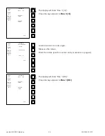
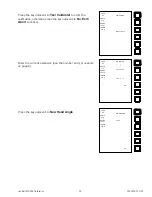
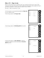
From the previous menu, press the key adjacent to 

Menu Up


to go to “10 Rope Limits”.

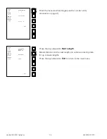
Press the key adjacent to 

10 Rope Limits

.

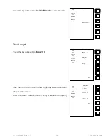
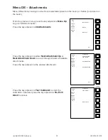
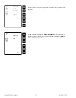
Press the key adjacent to 

Enter RopeLim0

 (front winch).

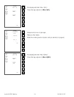
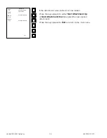
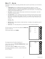
Press the key adjacent to 

Yes! Calibrate!

 to start the 

calibration, otherwise press the key adjacent to 

No, Exit/

Abort

 to cancel.

LOAD

0.8

ANGLE

41.8

RADIUS

76.2 FT

LENGTH

106.0

10 Rope Limits

Menu Up

Menu Down

Exit

LOAD

0.8

ANGLE

41.8

RADIUS

76.2 FT

LENGTH

106.0

Enter RopeLim0

16.800

Exit

LOAD

0.8

ANGLE

41.8

RADIUS

76.2 FT

LENGTH

106.0

YES! Calibrate!

NO, Exit  /  Abort

Summary of Contents for MG-534

Page 1: ...Link Belt MG 534 Rated Capacity Indicator System Calibration...

Page 2: ......

Page 3: ...14 Boom Extension Sensor Zero 14 Boom Angle Sensor Zero 15 Menu 03 Span 17 Boom Angle Sensor 17 Boom Extension Sensor 18 Menu 04 Swing Pot Zero 20 Swing Pot Zero 20 Swing Pot Direction 21 Menu 05 Main...

Page 4: ...Link Belt MG 534 Calibration ii W450160 10 07...

Page 5: ...23 Typical Tape Measure graduated in inches Tape Measure graduated in tenths of a foot Note The computer calculates measurements in feet and tenths of a foot so having the correct measure will facilit...

Page 6: ...ss the key adjacent to the number entry field enter key to enter the number If an error is made in data entry selecting the symbol and pressing the enter key will delete one character Selecting the C...

Page 7: ...ad Limit Indicator notifies the operator of load limit approaching overload amber lights and overload red lights The Menu Select Data Entry keys are used to select configuration and select menus and d...

Page 8: ...ctions described in this manual requires that the system be in the calibration mode of operation From the normal working screen press the Display Select key Press the key adjacent to Enter Calibration...

Page 9: ...f the sequence is incorrect or if the sequence is not entered within 5 seconds calibration will be aborted and the normal working screen will appear mWarning When in the calibration mode the two block...

Page 10: ...which the current error condition as well as the unit serial number and program information will be displayed Press the key adjacent to Exit to return to the main menu 00 Error Codes Menu Up Menu Down...

Page 11: ...Sensor Pendulum on page 32 Checking the Angle Sensor Drive Voltage on page 33 and Checking the Angle Sensor Voltage on page 33 of the Trouble shooting manual W450161 009 X X Replace computer 010 X X...

Page 12: ...Extension Sensor Drive Voltage on page 30 Checking the Boom Extension Sensor Voltage on page 30 Checking the Angle Sensor Drive Voltage on page 33 Checking the Angle Sensor Volt age on page 33 and Sw...

Page 13: ...uter 002 X 003 X X 004 X 005 X X 006 X X 007 X X X 008 X Refer to Anti Two Block Function on page 41 of the Troubleshooting manual W450161 009 X X Replace computer 010 X X 011 X X X 012 X X 013 X X X...

Page 14: ...5 X X Replace system chip Refer to System Chip IC16 on page 20 of the Trouble shooting manual W450161 006 X X 007 X X X 008 X Reset crane data 009 X X Replace system chip Refer to System Chip IC16 on...

Page 15: ...ength Chart Not Found Action 000 No Fault Found None 001 X Check other sensor faults Reselect crane setup 002 X Boom length is out of range for selected chart Check crane setup boom length and boom ex...

Page 16: ...w or prototype system before beginning calibration or testing From the previous menu press the key adjacent to Menu Up to go to 01 Crane Data Press the key adjacent to 01 Crane Data The current crane...

Page 17: ...play should show Personality good If the display shows Personality bad repeat the calibration sequence If the display continues to show Personality bad contact your service representative Press the ke...

Page 18: ...retracted before performing this calibration Boom extension sensor Analog Input 2 Boom angle sensor Analog Input 3 Boom Extension Sensor Zero From the previous menu press the key adjacent to Menu Up...

Page 19: ...o go to the next sensor to be zeroed Boom Angle Sensor Zero Using a digital level or inclinometer set the boom to zero degrees 0 Press the key adjacent to Zero No 3 X where X actual input LOAD 0 8 ANG...

Page 20: ...y adjacent to No Exit Abort to cancel When it has finished the display should show Zero No 3 0 Press the key adjacent to Exit to return to the main menu LOAD 0 8 ANGLE 41 8 RADIUS 76 2 FT LENGTH 106 0...

Page 21: ...e previous menu press the key adjacent Menu Up to go to 03 Span Sensor Press the key adjacent to 03 Span Sensor Press the key adjacent to Span No 3 X XX where X XX actual input Enter the measured angl...

Page 22: ...the distance from the boom pivot to the hook centerline T Calculate the span by subracting the fully retracted length from the fully extended length T S span 1 With the boom still fully extended cali...

Page 23: ...ut Press the key adjacent to Exit to return to the menu At this stage of the procedure the boom length display will indicate the fully extended boom length Retract the boom and continue the procedure...

Page 24: ...the right will cause the readout to increase Conversly rotating the boom in a counterclockwise direction to the left will cause the readout to decrease If the swing potentiometer is connected in such...

Page 25: ...on the display should increase from zero to 10 to show approximately ten degrees If the numbers decrease from 359 to 340 press the key adjacent to Direction to reverse the direction shown on the displ...

Page 26: ...the warning message poor angle If this message is displayed because of an error it can be corrected The procedure may then be continued using corrected data If this message is displayed due to requir...

Page 27: ...as 0 Enter the radius use the number entry procedure on page 2 LOAD 0 0 ANGLE 5 0 RADIUS 31 8 FT LENGTH 38 0 Radius Mom TareLoad 0 1 2 3 4 5 6 5 7 8 9 C Exit LOAD 0 0 ANGLE 5 0 RADIUS 31 8 FT LENGTH 3...

Page 28: ...y procedure on page 2 The display will show Bas 0 DU Press the key adjacent to Bas 0 DU LOAD 0 0 ANGLE 5 0 RADIUS 31 8 FT LENGTH 38 0 Radius Mom Redo Last Length Bas 0 D Redo This Length Exit LOAD 21...

Page 29: ...the boom to 50 percent Measure the radius Enter the radius use the number entry procedure on page 2 LOAD 21 1 ANGLE 67 4 RADIUS 10 7 FT LENGTH 38 0 Radius Mom Yes Calibrate NO Exit Abort LOAD 0 5 ANG...

Page 30: ...edure on page 2 The display will show Bas 1 DU Press the key adjacent to Bas 1 DU LOAD 0 5 ANGLE 10 0 RADIUS 67 5 FT LENGTH 75 0 Radius Mom Redo Last Length Bas 1 U Redo This Length Exit LOAD 0 5 ANGL...

Page 31: ...y extend the boom Measure the radius Enter the radius use the number entry procedure on page 2 Radius Mom Yes Calibrate NO Exit Abort LOAD 0 5 ANGLE 10 0 RADIUS 67 5 FT LENGTH 75 0 LOAD 0 5 ANGLE 10 0...

Page 32: ...dure on page 2 The display will show Bas 2 DU Press the key adjacent to Bas 2 DU LOAD 0 4 ANGLE 10 0 RADIUS 106 9 FT LENGTH 115 0 Radius Mom Redo Last Length Bas 2 D Redo This Length Exit LOAD 0 5 ANG...

Page 33: ...Link Belt MG 534 Calibration 29 W450160 10 07 Press the key adjacent to Yes Calibrate to store the data Radius Mom Yes Calibrate NO Exit Abort LOAD 0 5 ANGLE 64 1 RADIUS 43 9 FT LENGTH 115 0...

Page 34: ...ed from the centerline of rotation to the center of the load If the radius is already correct skip this procedure From the previous menu press the key adjacent to Menu Up to go to 06 Boom Defl n Press...

Page 35: ...data below 60 the warning message poor angle will appear Use the high angle or low angle arrow key to identify the angle related to the entry When this message occurs as the result of an error correc...

Page 36: ...ith the boom fully retracted From the previous menu press the key adjacent to Menu Up to go to 07 Head Angle Press the key adjacent to 07 Head Angle Press the key adjacent to Len 0 to calibrate the fi...

Page 37: ...to cancel Enter the current extension use the number entry procedure on page 2 Press the key adjacent to New Head Angle LOAD 0 8 ANGLE 41 8 RADIUS 76 2 FT LENGTH 106 0 YES Calibrate NO Exit Abort LOA...

Page 38: ...t Length Extend the boom to the next length and continue entering data for up to seven lengths Press the key adjacent to Exit to return to the main menu LOAD 0 8 ANGLE 41 8 RADIUS 76 2 FT LENGTH 106 0...

Page 39: ...Attachment Down to scroll through the list af available attachments Press the key adjacent to the desired attachment Press the key adjacent to Yes Calibrate to start the calibration otherwise press t...

Page 40: ...the key adjacent to either Next Attachment Up or Next Attachment Down to select the next desired attachment Press the key adjacent to Exit to return to the main menu LOAD 0 8 ANGLE 41 8 RADIUS 76 2 F...

Page 41: ...s Press the key adjacent to the desired winch Press the key adjacent to Yes Calibrate to start the calibration otherwise press the key adjacent to No Exit Abort to cancel LOAD 0 8 ANGLE 41 8 RADIUS 76...

Page 42: ...den Press the key adjacent to the desired winch or press the key adjacent to Change Winch to go to change the desired winch or press the key adjacent to Exit to return to the main menu LOAD 0 8 ANGLE...

Page 43: ...ered as 11 700 From the previous menu press the key adjacent to Menu Up to go to 10 Rope Limits Press the key adjacent to 10 Rope Limits Press the key adjacent to Enter RopeLim0 front winch Press the...

Page 44: ...ress the key adjacent to Enter RopeLim1 rear winch to enter the next rope limit or press the key adjacent to Exit to return to the main menu LOAD 0 8 ANGLE 41 8 RADIUS 76 2 FT LENGTH 106 0 Enter Rope...

Page 45: ...linders Two alarms are used to warn the operator of the approach to this potential damage these are swing arc and boom angle These alarms are preset for Low arc 70 Low ang 4 5 Alternate chart allows a...

Page 46: ...t to move through the alarms until the last alarm Alt Chart is shown Press the key adjacent to Exit to return to the main menu LOAD 0 8 ANGLE 41 8 RADIUS 76 2 FT LENGTH 106 0 Alarms Alt Chart y n YES...

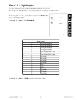
Page 47: ...Menu Up to go to 12 Digital I O Press the key adjacent to 12 Digital I O Digital Inputs 0 Swing Switch Inputs 1 Swing Switch Inputs 2 Swing Switch Inputs 3 Swing Switch Inputs 4 Interlock Alt Chart In...

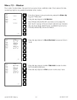
Page 48: ...BDC F Factor for the currently selected fly can also be viewed Press the key adjacent to Boom Number to view each boom mode Press the key adjacent to either Extension to view the data for the enabled...

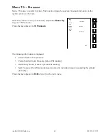
Page 49: ...5 Pressure Press the key adjacent to 15 Pressure The following information is displayed Current System Temperature Piston Side Hydraulic Pressure actual PSI reading Rod Side Hydraulic Pressure actual...

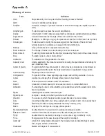
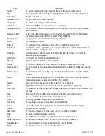
Page 50: ...of a body may be considered as concentrated so that if supported at this point the body would remain in equilibrium in any position Commissioning Preparing to be put into service Configuration The pos...

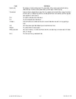
Page 51: ...distance from the centerline of rotation to the center of the hook Rated capacity The lifting capacity of a crane as determined by the manufacturer s published capacity chart Rated capacity The load...

Page 52: ...a different system as a loudspeaker that is actuated by electrical signals and supplies acoustic power Tx 0 The piston side pressure transducer Tx 1 The rod side pressure transducer Unladen A boom tha...

Page 53: ...Link Belt MG 534 Calibration A 4 W450160 10 07...

Page 54: ......

Page 55: ......

Page 56: ...45 Greer Company is a part of Tulsa Winch Group www team twg com As a leader in product innovation Greer Company is committed to the ongoing improvement of its equipment We reserve the right to make c...

Reviews: