background image

on slopes requires extra caution. If you feel uneasy on a

slope, do not mow it.
Do:
• Mow across the face of slopes; never mow up and

down. Exercise extreme caution when changing

direction on slopes.

• Watch for holes, ruts, rocks, hidden objects, or

bumps which can cause you to slip or trip. Tall grass

can hide obstacles.

Do not:
• Do not mow excessively steep slopes.
• Do not mow near drop-offs, ditches or

embankments; you could lose your footing or

balance.

• Do not mow slopes greater than 15 degrees.
• Do not mow on wet grass. Unstable footing could

cause slipping.

4

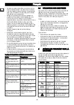
SYMBOLS ON THE PRODUCT

Some of the following symbols may be used on this tool.

Please study them and learn their meaning. Proper

interpretation of these symbols will allow you to operate

the tool better and safer.

Symbol

Name

Explanation

V

Volt

Voltage

A

Amperes

Current

Hz

Hertz

Frequency (cycles per

second)

W

Watt

Power

min

Minutes

Time

/min

Per Minute

Revolutions, strokes, sur-

face speed, orbits etc.,

per minute

Alternating

Current

Type of current

Direct Cur-

rent

Type or a characteristic

of current

no

No Load

Speed

Rational speed, at no

load

Safety Alert Precautions that involve

your safety.

Eye Protec-

tion

Always wear eye protec-

tion with side shields

marked to comply with

ANSI Z87.1 when operat-

ing this equipment.

WARNING

--- Wet Con-

ditions

Do not expose the prod-

uct to rain or moist condi-

tions.

Symbol

Name

Explanation

Read Opera-

tor’s Manual

To reduce the risk of in-

jury, user must read and

understand operator’s

manual before using this

product.

Maintain

Safety Devi-

ces

Do not open or remove

safety devices while the

tool is running.

Looking Be-

hind While

Backing

Look down and behind

first to avoid tripping

when pulling back.

DANGER ---

Keep Hands

and Feet

Away

To reduce the risk of in-

jury, keep hands and feet

away from rotating parts.

Do not operate unless

discharge cover or grass

bag is in its proper place.

If damaged, replace im-

mediately.

DANGER ---

Keep By-

standers

Away

All visitors should be kept

at a distance from work

area.

DANGER ---

Thrown Deb-

ris

Remove objects that can

be thrown by the blade in

any direction. Wear safe-

ty glasses.


DANGER ---

Steep Slope

Hazard

Use extra caution on

slopes. do not mow

slopes greater than 15

degrees.

5

RISK LEVELS

The following signal words and meanings are intended

to explain the levels of risk associated with this product.

SYM-

BOL

SIGNAL

MEANING

DANGER

Indicates an imminently

hazardous situation,which,

if not avoided, will result in

death or serious injury.

WARNING

Indicates a potentially haz-

ardous situation,which, if

not avoided, could result in

death or serious injury.

CAUTION

Indicates a potentially haz-

ardous situation, which, if

not avoided, may result in

minor or moderate injury.

7

English

EN

Summary of Contents for MO80L00

Page 1: ... 保证色块朝外 3 单色印刷 要求无色差 无污点 4 骑马钉 裁切均匀 无连页 5 以封样为准 1 材质要求 60g双胶纸 常州格力博集团 说明书 许乃鑫 陈丽 周艳 王小妮 李海平 20 10 20 版本号 描 复 日 期 工艺 审核 校对 设计 标记处数 签名 日期 阶段标记 视角标记 重量 比例 批准 审定 标准化 日期 更改文件号 SCALE A5 210mm 145mm 6 料件需符合格力博HSF文件 编号 GLB CGR 146 里关于环保和有害物质的具体要求 A B B 许乃鑫 1 20 10 20 此为 P0800716 00编号升级版本 设变LOGO ...

Page 2: ...LMB408 MO80L00 EN OPERATOR MANUAL LAWN MOWER MANUEL D UTILISATION FR TONDEUSE MANUAL DEL OPERADOR ES CORTACÉSPED www greenworkstools com 80v pro ...

Page 3: ......

Page 4: ...stall the mulch plug 9 7 6 Install the side discharge chute 9 7 7 Set the blade height 10 7 8 Install the battery pack 10 7 9 Remove the battery pack 10 8 Operation 10 8 1 Start the machine 10 8 2 Stop the machine 11 8 3 Operate the self propel system 11 8 4 Empty the grass catcher 11 8 5 Operate on slopes 11 8 6 Operation tips 11 9 Maintenance 11 9 1 General maintenance 12 9 2 Replace the blade 1...

Page 5: ...ne enters the area Never allow children under 14 years old to operate a power mower Operators 14 years old and over should fully read and understand the operator s manual and safety rules Only responsible individuals who are familiar with these rules of safe operation should be allowed to use this machine 3 2 GENERAL OPERATION Read this operator s manual carefully in its entirety before assembling...

Page 6: ...ase the bail switch to disengage the motor Remove the battery Inspect for damage Repair any damaged parts before restarting and operating the lawn mower Have servicing performed by a qualified repair person using only identical replacement parts This will ensure that the safety of the product is maintained Dress properly do not wear loose clothing or jewelry that can be caught in moving parts Use ...

Page 7: ...r tamper with safety devices Check their proper operation regularly Never do anything to interfere with the intended function of a safety device or to reduce the protection provided by a safety device Keep machine free of grass leaves or other debris build up Allow machine to cool before storing Never make any adjustments or repairs with the motor running Always remove battery pack from mowers bef...

Page 8: ...rat ing this equipment WARNING Wet Con ditions Do not expose the prod uct to rain or moist condi tions Symbol Name Explanation Read Opera tor s Manual To reduce the risk of in jury user must read and understand operator s manual before using this product Maintain Safety Devi ces Do not open or remove safety devices while the tool is running Looking Be hind While Backing Look down and behind first ...

Page 9: ...copic particles Save these instructions 7 INSTALLATION WARNING Do not change or make accessories that are not recommended by the manufacturer WARNING Do not put in the safety key or the battery pack until you assemble all the parts 7 1 UNPACK THE MACHINE WARNING Make sure that you correctly assemble the machine before use WARNING If the parts have damage do not use the machine If you do not have a...

Page 10: ...nd engage the hooks 19 on the door rod 18 5 Close the rear discharge door 17 7 5 INSTALL THE MULCH PLUG 1 Remove the grass catcher 2 Open the rear discharge door 17 and hold it 3 Hold the mulch plug 11 by its handle 21 and fit it in the discharge chute 4 Close the rear discharge door 7 6 INSTALL THE SIDE DISCHARGE CHUTE CAUTION When you use the side discharge chute do not install the grass catcher...

Page 11: ... the battery pack 25 with the grooves in the battery compartment 3 Push the battery pack into the battery compartment until the battery pack locks into place 4 When you hear a click the battery pack is installed 5 Close the battery door NOTE The motor starts only when you put in the safety key 26 7 9 REMOVE THE BATTERY PACK 1 Open the battery door 8 2 Remove the safety key 26 3 Push and hold the b...

Page 12: ...he self propel system 8 4 EMPTY THE GRASS CATCHER 1 Stop the machine 2 Remove the battery pack 3 Open the rear discharge door and hold it 4 Hold the grass catcher by its handle and unhook it from the door rod 5 Close the rear discharge door 6 Empty the grass catcher 8 5 OPERATE ON SLOPES WARNING Do not mow on the slopes with incline more than 15 If you are not comfortable do not mow on a slope WAR...

Page 13: ... 30 with a wrench 28 or socket 7 Remove the blade 29 and the fan 31 8 Put back the fan 9 Position a new blade with the cutting edges toward the ground 10 Tighten the mounting screw 9 3 STORE THE MACHINE Clean the machine before storage Make sure the motor is not hot when you store the machine Make sure that the machine does not have loose or damaged parts If it is necessary do these steps instruct...

Page 14: ...y pack 3 Disconnect the power source 4 Inspect for damage 5 Repair the machine be fore you start it again Problem Possible cause Solution The machine stops during mowing The blade height is too low Increase the blade height The battery pack is out of power Charge the bat tery pack The grass clip pings attach to the deck or the blade Remove the bat tery pack and check the deck Operation tem peratur...

Page 15: ... and or maintained in accordance with the owner s manual or 3 Normal wear except as noted below 4 Routine maintenance items such as lubricants blade sharpening 5 Normal deterioration of the exterior finish due to use or exposure HELPLINE Warranty service is available by calling our toll free helpline at 1 855 345 3934 TRANSPORTATION CHARGES Transportation charges for the movement of any power equi...

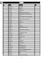
Page 16: ...1 82 83 75 24 42 20 21 22 52 53 25 84 85 86 No Part No Description Qty 1 32202390A Bolt 2 2 341281179 8 Wheel assembly 2 3 332211179 Washer 2 4 311021179 Front wheel axle 1 5 341602376AB 10 Wheel assembly 2 6 341041531 Big gear 2 7 322081163 Screw 30 8 341021531AD Dust cover 2 9 3220505D Screw 6 10 341221531 Bearing holder 2 11 321011531 Bearing 2 12 311083431 Rear wheel axle 1 13 32905302A Retain...

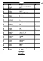
Page 17: ... Rear baffle 1 30 332081531 Height adjustment link bar 1 31 3221637 Bolt 4 32 333041519D Height adjustment bracket left 1 33 32910131 Nut 4 34 332041179 Press board rear shield 1 35 342011179 Rear shield 1 36 349011179K Gear box 1 37 332031179 Gear box bracket 1 38 341061179C Bumper 1 39 3220504 Screw 4 40 341331179J Bumper cover 1 41 341021179 Front panel 1 42 33307470 Axle press plate 2 43 32209...

Page 18: ... 2 66 332101179C Block 2 67 32233684 Washer 2 68 322031179 Bolt 2 69 341151546 Knob 2 70 332061179 Spring pin 2 71 332071179C Limit column 2 72 332081179C Fixed base limit pillar 2 73 332051179 Compression spring 2 74 341381179 Washer 2 75 333121179A Lower handle 2 76 341291179 Knob 2 77 322041179 Bolt 2 78 341031555 Insulation sleeve 2 79 332151531 Upper handle 1 80 311071179 Switch box assembly ...

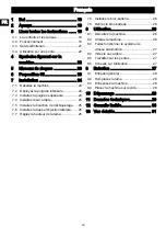
Page 19: ...uchon de déchiquetage 25 7 6 Installez la trappe d éjection latérale 25 7 7 Réglez la hauteur de la lame 25 7 8 Installez le bloc batterie 26 7 9 Retirez le bloc batterie 26 8 Utilisation 26 8 1 Démarrez la machine 26 8 2 Arrêtez la machine 26 8 3 Faites fonctionner le système de vitesse automotrice 27 8 4 Videz le sac arrière 27 8 5 Travaillez sur les pentes 27 8 6 Conseils sur l utilisation 27 9...

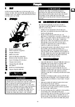
Page 20: ...t lorsque vous approchez un angle mort une porte un arbuste un arbre ou tout autre objet qui pourrait obscurcir votre vision d un enfant ou d un curieux Gardez les enfants les curieux les assistants et les animaux domestiques à au moins 30 m 100 pi de la tondeuse lorsqu elle est en marche Arrêtez la machine si quelqu un s approche Ne permettez jamais à des enfants de moins de 14 ans d utiliser une...

Page 21: ...qui pourrait faire ricocher le produit déchargé vers l opérateur Pour éviter la lame ou une blessure par un objet projeté restez dans la zone de l opérateur derrière les guidons Un couvercle de décharge manquant ou endommagé peut causer un contact avec la lame ou des blessures causées par des objets projetés Les objets heurtés par la lame de la tondeuse à gazon peuvent causer de graves blessures a...

Page 22: ...ont corrosifs et peuvent causer des dommages aux yeux ou à la peau s ils sont rejetés L électrolyte peut être toxique lorsqu elle est avalée Dans des conditions abusives du liquide peut être éjecté de la batterie évitez tout contact En cas de contact accidentel rincez avec de l eau En cas de contact avec les yeux consultez également un médecin Le liquide s échappant des batteries peut causer des i...

Page 23: ...char geur 39 F 4 C 113 F 45 C Plage de température d entreposage de la batt erie 1 an 32 F 0 C 73 F 23 C 3 mois 32 F 0 C 113 F 45 C 1 mois 32 F 0 C 140 F 60 C Plage de température de déchargement de la batt erie 6 8 F 14 C 167 F 75 C 3 4 UTILISATION SUR UNE PENTE Les pentes sont un facteur majeur lié aux accidents de glissade et de chute qui peuvent entraîner des blessures graves L utilisation sur...

Page 24: ...r but d expliquer les niveaux de risques associés à l utilisation de ce produit SYM BOLE SIGNAL SIGNIFICATION DANGER Indique une situation dan gereuse imminente qui si elle n est pas évitée peut entraîner la mort ou des blessures graves AVERTISSE MENT Indique une situation po tentiellement dangereuse qui si elle n est pas évitée peut entraîner la mort ou des blessures graves MISE EN GARDE Indique ...

Page 25: ...les pièces non assemblées de la boîte 4 Retirez la machine de sa boîte 5 Jetez la boîte et l emballage en respectant les règlements locaux 7 2 DÉPLOYEZ LA POIGNÉE INFÉRIEURE 1 Tirez et tournez les boutons de la poignée 13 de 90 2 Déployez la poignée inférieure 3 3 Alignez les boutons de la poignée dans l une des trois positions 14 sur les supports 4 Tournez les boutons de la poignée de 90 jusqu à ...

Page 26: ...r sa poignée 21 et insérez le dans la goulotte d éjection 4 Fermez la trappe d éjection arrière 7 6 INSTALLEZ LA TRAPPE D ÉJECTION LATÉRALE ATTENTION Lorsque vous utilisez la trappe d éjection latérale n installez pas le sac arrière laissez le bouchon de déchiquetage en place 1 Ouvrez et retenez la trappe d éjection latérale 9 2 Alignez les recoins de la trappe d éjection latérale 12 sous la charn...

Page 27: ...sque le bloc batterie sera inséré correctement 5 Fermez la trappe de la batterie REMARQUE Le moteur ne démarre que lorsque vous insérez la clé de sécurité 26 7 9 RETIREZ LE BLOC BATTERIE 1 Ouvrez la trappe de la batterie 8 2 Retirez la clé de sécurité 26 3 Poussez et maintenez enfoncé le bouton de déblocage de la batterie 24 4 Retirez le bloc batterie 25 de la machine 8 UTILISATION AVERTISSEMENT P...

Page 28: ... la machine 2 Retirez le bloc batterie 3 Ouvrez et retenez la trappe d éjection arrière 4 Tenez le sac arrière par sa poignée et décrochez le de la barre de la porte 5 Fermez la trappe d éjection arrière 6 Videz le sac arrière 8 5 TRAVAILLEZ SUR LES PENTES AVERTISSEMENT Ne tondez pas sur une pente inclinée à plus de 15 Si vous n êtes pas à l aise ne tondez pas sur une pente AVERTISSEMENT Lorsque v...

Page 29: ...ants épais ou enroulez la lame avec un chiffon lorsque vous la touchez 1 Arrêtez la machine 2 Assurez vous que la lame s est complètement arrêtée 3 Retirez la clé de sécurité et le bloc batterie 4 Tournez la machine sur le côté 5 Utilisez un morceau de bois 27 pour empêcher le mouvement de la lame 6 Retirez la vis de fixation 30 à l aide d une clé 28 ou d une douille 7 Retirez la lame 29 et le ven...

Page 30: ...uteur plus élevée La machine ne déchiquette pas correctement Des débris d herbe humide s accroche au plateau Attendez jusqu à ce que l herbe soit sèche avant la tonte Le bouchon de déchiquetage est manquant Installez le bou chon de déchi quetage Problème Cause possible Solution La machine est difficile à pouss er L herbe est trop haute ou la hau teur de la lame est trop basse Augmentez la hauteur ...

Page 31: ...ciales et qui ont été entretenus conformément aux instructions du manuel du propriétaire fourni avec le produit neuf ARTICLES NON COUVERTS PAR LA GARANTIE 1 Toute pièce qui est devenue inopérante en raison d une mauvaise utilisation d une utilisation commerciale d un abus d une négligence d un accident d un entretien inapproprié ou d une modification ou 2 L appareil s il n a pas été utilisé et ou ...

Page 32: ...1 22 52 53 25 84 85 86 No No de pièce Description Qté 1 32202390A Boulon 2 2 341281179 Roue de 8 po 2 3 332211179 Rondelle 2 4 311021179 Assemblage de l essieu avant 1 5 341602376AB Roue de 10 po 2 6 341041531 Grande engrenage 2 7 322081163 Vis 30 8 341021531AD Couvercle à poussière 2 9 3220505D Vis 6 10 341221531 Support de roulement 2 11 321011531 Palier 2 12 311083431 Axe de roue arrière 1 13 3...

Page 33: ...e de hauteur 1 31 3221637 Boulon 4 32 333041519D Plaquette de réglage de hauteur gauche 1 33 32910131 Écrou 4 34 332041179 Tableau de presse Bouclier arrière 1 35 342011179 Bouclier arrière 1 36 349011179K Sac à herbe 1 37 332031179 Support de sac de réception d herbe 1 38 341061179C Pare chocs 1 39 3220504 Vis 4 40 341331179J Capot décoratif 1 41 341021179 Panneau avant 1 42 33307470 Plaque de pr...

Page 34: ...2101179C Bloc 2 67 32233684 Rondelle 2 68 322031179 Boulon 2 69 341151546 Bouton 2 70 332061179 Goupille élastique 2 71 332071179C Colonne limite 2 72 332081179C Base fixée montant de limite 2 73 332051179 Ressort comprimé 2 74 341381179 Rondelle 2 75 333121179A Poignée inférieure 2 76 341291179 Bouton 2 77 322041179 Boulon 2 78 341031555 Gaine isolante 2 79 332151531 Partie supérieure du guidon 1...

Page 35: ...nstalación del conducto de descarga lateral 41 7 7 Ajuste de la altura de la cuchilla 41 7 8 Instalación de la batería 41 7 9 Retirada de la batería 42 8 Funcionamiento 42 8 1 Puesta en marcha de la máquina 42 8 2 Detención de la máquina 42 8 3 Funcionamiento del sistema de autopropulsión 42 8 4 Vaciado del recogehierba 43 8 5 Funcionamiento en pendientes 43 8 6 Consejos de funcionamiento 43 9 Man...

Page 36: ...bjetos que puedan ocultar su visión de un niño o un transeúnte Mantenga a los niños los transeúntes los ayudantes y las mascotas al menos a 100 pies 30m del cortacésped cuando esté en funcionamiento Detenga la máquina si alguien entra en la zona Nunca permita que niños menores de 14 utilicen un cortacésped eléctrico Los operarios de 14 años en adelante deben leer y entender en su totalidad el manu...

Page 37: ...r contacto con la cuchilla o lesiones por objetos proyectados Los objetos golpeados por la cuchilla del cortacésped pueden producir lesiones graves a las personas El césped siempre debe examinarse detenidamente y deben eliminarse todos los objetos antes de cada corte Detenga la cuchilla cuando cruce senderos de grava aceras o caminos Siga todas las instrucciones de carga y no cargue la batería o e...

Page 38: ...rior a 130 C puede provocar una explosión La temperatura de 130 C puede sustituirse por la temperatura de 265 F Tenga cuidado al manipular las baterías para evitar un cortocircuito con materiales conductores como anillos pulseras llaves etc La batería o el conductor puede sobrecalentarse y producir quemaduras si se hace contacto con dichos materiales No utilice una batería o un aparato que haya su...

Page 39: ...o en pendientes es necesario tomar precauciones adicionales Si no se siente seguro en una pendiente no la siegue Cosas que debe hacer En las pendientes debe segarse transversalmente nunca siegue hacia arriba y abajo Extreme las precauciones cuando cambie de dirección en pendientes Este atento por si hubiera agujeros surcos piedras objetos ocultos o baches que puedan hacer que resbale o tropiece La...

Page 40: ...O LO INDICACIÓN SIGNIFICADO ADVERTEN CIA Indica una situación de pel igro potencial que de no evitarse podría provocar lesiones graves o incluso la muerte PRECAU CIÓN Indica una situación de pel igro potencial que de no evitarse puede provocar lesiones leves o modera das PRECAU CIÓN Sin símbolo de alerta so bre seguridad Indica una situación que puede provo car daños materiales 6 PROPUESTA 65 AVIS...

Page 41: ...s del asa en una de las tres posiciones 14 en los soportes 4 Gire los mandos de las asas 90 hasta que encajen en los orificios de los soportes NOTA Asegúrese de que los dos mandos de las asas estén en la misma posición AVISO No dañe ni pellizque los cables cuando pliegue o despliegue el asa 7 3 INSTALACIÓN DEL ASA SUPERIOR 1 Alinee los orificios del asa superior 2 y el asa inferior 3 2 Introduzca ...

Page 42: ...a puerta de descarga lateral 9 7 7 AJUSTE DE LA ALTURA DE LA CUCHILLA La máquina puede ajustarse a distintas alturas de cuchilla 1 Tire hacia atrás de la palanca de ajuste de altura 7 para aumentar la altura de la cuchilla 2 Tire hacia delante de la palanca de ajuste de altura para disminuir la altura de la cuchilla 7 8 INSTALACIÓN DE LA BATERÍA AVISO Si la batería o el cargador ha sufrido daños s...

Page 43: ... Suelte el interruptor de seguridad para detener la máquina AVISO Espere hasta que las cuchillas se detengan por completo antes de volver a poner en marcha la máquina No apague y encienda la máquina rápidamente AVISO Retire siempre la batería tras finalizar el trabajo 8 3 FUNCIONAMIENTO DEL SISTEMA DE AUTOPROPULSIÓN NOTA La máquina está construida con un protector térmico para detener el motor aut...

Page 44: ...i pierde el equilibrio suelte el interruptor de seguridad inmediatamente No siegue cerca de precipicios zanjas o terraplenes 8 6 CONSEJOS DE FUNCIONAMIENTO No intente anular el funcionamiento del botón de puesta en marcha o el interruptor de seguridad No incline la máquina cuando la ponga en marcha No ponga las manos ni los pies cerca o debajo de las piezas giratorias Mantenga limpio el conducto d...

Page 45: ...iga estos pasos estas instrucciones Sustituya las piezas dañadas Apriete los pernos Hable con una persona de un centro de servicio aprobado Almacene la máquina en una zona seca Asegúrese de que los niños no puedan acercarse a la máquina 9 4 COLOCACIÓN DE LA MÁQUINA SOBRE UN EXTREMO 1 Retire el recogehierba 2 Tire de los mandos del asa 13 y gírelos 90 3 Pliegue el asa 4 Gire los mandos del asa 90 p...

Page 46: ...or 2 Retire la llave de se guridad y la batería 3 Desconecte la fuente de alimentación 4 Inspeccione si hay daños 5 Repare la máquina an tes de volver a ponerla en marcha Problema Posible causa Solución La máquina se detiene durante el segado La altura de la cuchilla es de masiado baja Aumente la al tura de la cuchil la La batería se ha agotado Cargue la bate ría Hay recortes de hierba adheridos a...

Page 47: ... La unidad si no ha sido utilizada o mantenida de acuerdo con el manual del propietario o 3 Desgaste normal excepto en lo indicado a continuación 4 Artículos de mantenimiento de rutina tales como lubricantes afilado de cuchillas 5 Deterioro normal del acabado exterior debido al uso o la exposición LÍNEA DE ASISTENCIA TELEFÓNICA Puede contactar con el servicio de garantía llamando a nuestra línea d...

Page 48: ... 84 85 86 Nº Nº pieza Descripción Cant 1 32202390A Tornillo 2 2 341281179 Conjunto de la rueda de 8 2 3 332211179 Arandela 2 4 311021179 Eje de rueda delantera 1 5 341602376AB Conjunto de la rueda de 10 2 6 341041531 Engranaje grande 2 7 322081163 Tornillo 30 8 341021531AD Cubierta antipolvo 2 9 3220505D Tornillo 6 10 341221531 Fijación de cojinete 2 11 321011531 Teniendo 2 12 311083431 Eje de rue...

Page 49: ...ra 1 30 332081531 Palanca de unión para ajustar la altura 1 31 3221637 Tornillo 4 32 333041519D Soporte de ajuste de altura izquierda 1 33 32910131 Tuerca 4 34 332041179 Junta de sujeción Protector trasero 1 35 342011179 Protector trasero 1 36 349011179K Caja de cambios 1 37 332031179 Soporte de la caja de cambios 1 38 341061179C Parachoques 1 39 3220504 Tornillo 4 40 341331179J Cubierta de parach...

Page 50: ...a 1 65 32201467 Tuerca 2 66 332101179C Bloque 2 67 32233684 Arandela 2 68 322031179 Tornillo 2 69 341151546 Perilla 2 70 332061179 El pasador de resorte 2 71 332071179C Columna de límite 2 72 332081179C Base fija del eje para marcar el límite 2 73 332051179 Primavera 2 74 341381179 Arandela 2 75 333121179A Manija inferior 2 76 341291179 Perilla 2 77 322041179 Tornillo 2 78 341031555 Manguito de ai...

Reviews: