background image

www.greenmasterfitness.com.tw 

13 


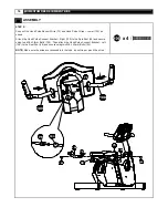
ASSEMBLY 

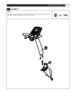
STEP 2: 


Slide the Computer Protect Cov er (45) onto the Console Upright Tube (43) and attach to the 
Computer – Bottom (42) with four 4 x 19mm Screws (46).


x4


42

43

46

45


Summary of Contents for Momentum RB5

Page 1: ...MOMENTUM RB5 RECUMBENT BIKE USER MANUAL...

Page 2: ...bly quick and hassle f ree Clear your work area Make sure that y ou hav e cleared away a large enough space to properly assemble the unit Make sure the space is free from anything that may cause injur...

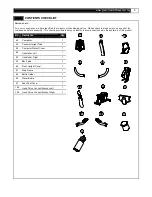
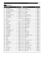
Page 3: ...ed to help you identify the components used in the assembly of this product No Description Qty 42 Computer 1 43 Console Upright Tube 1 45 Computer Protect Cover 1 48 Handlebar Left 1 50 Handlebar Righ...

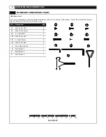
Page 4: ...this product This chart is prov ided to help you identify those items that may be unf amiliar to you No Description Qty 27 M8 x 10mm Bolt 6 44 M6 x 15mm Screw 2 46 4 x 19mm Bolt 4 100 M8 x 45mm Bolt...

Page 5: ...or System 1 RB5 015 49 Handlebar Casing 2 RB5 049 16 Fly wheel Axle 1 RB5 016 50 Handlebar Right 1 RB5 050 17 M6 Ny lon Nut 4 RB5 017 51 Saddle 1 RB5 051 18 Fly wheel Axle Fixing Plate 1 RB5 018 52 Ba...

Page 6: ...5mm Bolt 1 RB5 116 83 10 x 140mm Axle 1 RB5 083 117 M8 Ny lon Nut 1 RB5 117 84 Bottle Holder 1 RB5 084 118 8 x 70mm Axle 1 RB5 118 85 Water Bottle 1 RB5 085 119 8mm Washer 1 RB5119 86 Lev el Adjusters...

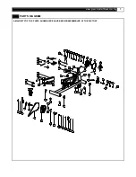
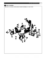
Page 7: ...TS SHOWN HERE HAVE BEEN PREASSEMBLED AT THE FACTORY 81 86 28 28 28 86 28 86 86 80 70 20 19 77 78 79 17 2 18 1 13 15 14 16 1 11 12 9 7 7 8 3 4 3 6 5 1 2 1 24 19 89 82 90 102 55 57 91 56 19 95 26 54 3 1...

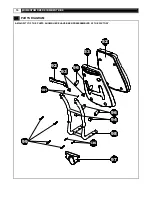
Page 8: ...8 MOMENTUM RB5 RECUMBENT BIKE PARTS DIAGRAM A MAJORITY OF THE PARTS SHOWN HERE HAVE BEEN PREASSEMBLED AT THE FACTORY 27 50 48 42 43 44 45 46 27 74 71 72 49 49 73...

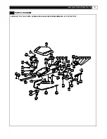
Page 9: ...HAVE BEEN PREASSEMBLED AT THE FACTORY 75 47 106 88 100 54 107 109 114 120 124 126 122 121 114123120 125 127 121 129 128 131 133 75 108 88 51 47 105 54 100 106 100 132 39 114 118 119 114 117 116 115 1...

Page 10: ...10 MOMENTUM RB5 RECUMBENT BIKE PARTS DIAGRAM A MAJORITY OF THE PARTS SHOWN HERE HAVE BEEN PREASSEMBLED AT THE FACTORY 99 92 53 52 96 93 101 94 96 98 97 136...

Page 11: ...m tw 11 PARTS DIAGRAM A MAJORITY OF THE PARTS SHOWN HERE HAVE BEEN PREASSEMBLED AT THE FACTORY 60 61 66 67 63 81 69 101 19 62 43 64 65 63 68 58 40 41 39 104 90130 83 76 130 90 63 104 19 104 101 19 19...

Page 12: ...the Console Upright Tube 43 and secure using two M6 x 15mm Bolts 44 Attach the Handlebar Left 48 to the Console Upright Tube 43 and secure using three M8 x 10mm Bolts 27 Attach the Handlebar Right 50...

Page 13: ...www greenmasterfitness com tw 13 ASSEMBLY STEP 2 Slide the Computer Protect Cov er 45 onto the Console Upright Tube 43 and attach to the Computer Bottom 42 with four 4 x 19mm Screws 46 x4 42 43 46 45...

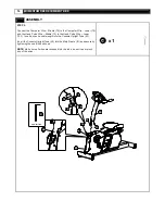
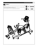
Page 14: ...3 to the Hand Pulse Wire Lower 103 Insert any extra cable length into the Console Upright Tube 43 Insert the Console Upright Tube 43 into the Main Frame 81 and secure by tightening the one Bolt as sho...

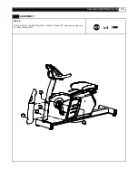
Page 15: ...www greenmasterfitness com tw 15 ASSEMBLY STEP 4 Attach the Front Upright Cover 62 to the Main Frame 81 and secure usingf our 4 x 9mm Screws 101 x4 81 62 101 101 101...

Page 16: ...Pulse Connect Bracket Right 109 to the Seat Post 39 and secure using two M8 x 50mm Bolts 100 Then attach the Hand Pulse Connect Bracket Left 108 to the Seat Post 39 and secure using two M8 x 50mm Bolt...

Page 17: ...SSEMBLY STEP 6 Attach the Back Pad Support Tube 98 to the Seat Post 39 and secure using four M8 x 50mm Bolts 100 and two M8 x 25mm Bolts 136 Attach the Seat Post Cov er 97 to the Back Pad Support Tube...

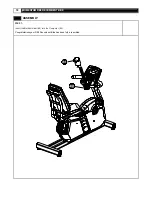
Page 18: ...18 MOMENTUM RB5 RECUMBENT BIKE ASSEMBLY STEP 7 Insert the Bottle Holder 84 into the Computer 42 Congratulations your RB5 Recumbent Bike has been fully assembled...

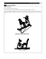
Page 19: ...recumbent bikes on its side Tip the recumbent bike to the left right You will then see the LEVEL ADJUSTERS These will need to be screwed either in or out to lev el the recumbent bike Repeat for the ot...

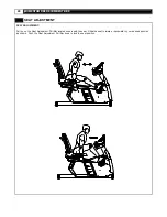
Page 20: ...AT ADJUSTMENT SEAT ADJUSTMENT Pull up on the Seat Adjustment Pull Bar located underneath the seat Slide the seat f orward or backward toy our desired position as shown Push the Seat Adjustment Pull Ba...

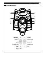
Page 21: ...rfitness com tw 21 COMPUTER OPERATION G M L K J I H F E D C B A LOAD DENSITY A B SPEED RPM TIME WATTS C D PRESET PROGRAMS UP E F STOP MODE G H DISTANCE PACE CALORIES PULSE I J PRESET PROGRAMS DOWN K L...

Page 22: ...t resistance level from 1 to 20 DISTANCE Count up this measures the total distancef rom 0 to 99 9 Km Mile Count down if y ou hav e set the target distance the computer will count down f rom that prese...

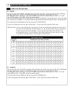
Page 23: ...ess START to begin the exercise program The TIME will start to count down to 0 00 then the program will stop automatically To increase or decrease the resistance while exercising press the UP DOWN but...

Page 24: ...e for less than 20 minutes the computer will operate in 1 minute interv als for each section display ed until the time runs out i e input 12 minutes and the program will run for 12 sections at 1 minut...

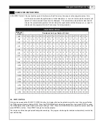
Page 25: ...11 9 11 9 11 9 11 9 11 9 11 9 11 9 11 L 10 10 12 10 12 10 12 10 12 10 12 10 12 10 12 10 12 10 12 10 12 L 11 11 13 11 13 11 13 11 13 11 13 11 13 11 13 11 13 11 13 11 13 L 12 12 14 12 14 12 14 12 14 12...

Page 26: ...HRC FAT BURN button the display will show the def ault user profile Input the user prof ile then the TIME display will show a blinking 30 00 Press the UP DOWN button to adjust the workout time then pr...

Page 27: ...ual user heart rate reaches the target heart rate If the actual user heart rate is under the target heart rate the resistance will increase by one more lev el ev ery 30 seconds The aim of this program...

Page 28: ...exercise only for af ew minutes iny our target zone Howev er y our aerobic f itness will improv e ov er the next six to eight weeks Don t be discouraged if it takes longer It s important to work at yo...

Page 29: ...condition To determine your target zone consult the chart we hav e prov ided FIND YOUR TARGET HEART RATE 200 180 160 140 120 100 YOUR HEART RATE in beats per minute 80 20 25 30 35 40 45 50 55 60 65 70...

Page 30: ...develop the upper and lower body muscle groups These muscle groups are shown in gray color on the chart below Shoulder muscles A B Pectoral muscles Bicep muscle C D Abdominal muscles Forearm muscles...

Page 31: ...nner Thigh Stretch Sit with the soles of y ourf eet together withy our knees pointing outward Pully our f eet as close intoy our groin as possible Gently push y our knees towards the floor Hold f or 1...

Page 32: ...Industrial Corp All rights reserv ed MOMENTUM SERIES products are manuf actured by GREENMASTER INDUSTRIAL CORP No 1 Lane 233 Sec 2 Charng Long Road Taiping City Taichung Hsien Taiwan R O C Website www...

Reviews: