background image

Greenlee Textron / Subsidiary of Textron Inc.

3

4455 Boeing Dr., Rockford, IL 61109-2988   815/397-7070

Orchard and Shade Tree Pruner

Safety is a critical factor in the design of Greenlee equipment. The best program starts with a safety-conscious
operator. The information highlighted in this bulletin describes operating practices for the benefit of the workers
who will use our equipment in their daily jobs. Comments from users are appreciated.

The symbol above is used to call your attention
to instructions concerning your personal safety.
Watch for this symbol. It points out important safety
precautions. It means “ATTENTION! Become alert!
Your personal safety is involved!”
 Read the
message that follows and be alert to the possibility
of personal injury or death.

Hazards or unsafe practices which, if not avoided, COULD
result in minor personal injury or property damage.

Hazards or unsafe practices which, if not avoided, COULD
result in severe personal injury or death.

Immediate hazards which, if not avoided, WILL result in
severe personal injury or death.

SAFETY
ALERT
SYMBOL

Additional copies of this manual are available upon request at no charge.

SAVE THESE INSTRUCTIONS

A person who has not read and does not understand all
operating instructions is not qualified to operate this tool.

Failure to read and understand safety instructions may
result in injury or death.

IMPORTANT SAFETY INSTRUCTIONS

Summary of Contents for LHFS-210001

Page 1: ...FAIRMONT Read and understand this material before operating or servicing this pruner Failure to understand how to safely operate this pruner could result in an accident causing serious injury or death ORCHARD AND SHADE TREE PRUNER Closed Center Conversion Part Included LHFS 210001 LHFS 210002 LHFS 210003 LHFS 210005 ...

Page 2: ...l or replacement manuals may be obtained from your Greenlee Fairmont distributor When tool is received complete the following record SERIAL NUMBER ____________________________ DATE OF PURCHASE _________________________ WHERE PURCHASED ________________________ Always mention the tool s serial number when ordering or writing about parts For convenience in ordering parts are listed by part number des...

Page 3: ...tions It means ATTENTION Become alert Your personal safety is involved Read the message that follows and be alert to the possibility of personal injury or death Hazards or unsafe practices which if not avoided COULD result in minor personal injury or property damage Hazards or unsafe practices which if not avoided COULD result in severe personal injury or death Immediate hazards which if not avoid...

Page 4: ...jury from flying debris or hydraulic fluid Do not disconnect tool hoses or fittings while the power unit is running or if the hydraulic fluid is hot Exposure to hot hydraulic fluid can cause serious burns Do not reverse hydraulic flow Operation with hydraulic flow reversed can cause tool mal function Always connect supply pressure hoses and return tank hose to proper tools ports Failure to observe...

Page 5: ...perator s comfort and safety The LHFS is available in four different models with lengths ranging from 42 inches to 78 inches for various tree trimming requirements The cutter unit made of forged alloy steel for long cutting edge life can trim branches up to 1 3 4 inches in diameter Identification Electrical Shock Hazard This is not an insulated tool Do not use near electrical lines Contact with li...

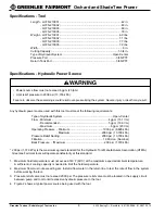
Page 6: ...nstall a flow meter in the return line to test the rate of flow in the system before working the tool 3 Pressure relief valve must not exceed 2000 psi The pressure relief valve must be located in the supply circuit between pump and tool to limit excessive hydraulic pressure to the tool 4 Figure 2 shows a typical power source being used with the tool Type of Hydraulic System Open Center Flow Minimu...

Page 7: ...L VALVE FLOW METER T P TOOL RESERVOIR PUMP POWER SOURCE Figure 2 Hydraulic Schematic Recommended Hydraulic Fluids Any non detergent hydraulic fluid which meets the following specifications or HTMA specifications may be used S U S 100 F 38 C 140 to 225 210 F 99 C 40 minimum Flash Point 340 F min 170 C min Pour Point 30 F min 34 C min Specifications Hydraulic Power Source cont d ...

Page 8: ...ol Failure to observe this warning could result in severe injury or death Connecting Hoses see Figures 1 2 1 Stop the power source 2 Connect the return tank hose from the power source port T to the tool T port Note Return tank hose connection should always be connected before supply pressure hose connection to prevent pressure build up inside the tool 3 Connect the supply pressure hose from the po...

Page 9: ... The cutter blade 7 will slice through the limb and come to a stop 4 To return the cutter blade 7 to the starting position release the trigger 6 5 Lay the tool on a flat surface when not in use 6 When the tool is not in use stop the power source to reduce heat and wear on the tool components Electrical Shock Hazard This is not an insulated tool Do not use near electrical lines Contact with live ci...

Page 10: ...g and sliding surfaces several times every operating day with 20W or 30W oil Apply a heavy coating to these surfaces before storing 4 Several times a day the blade and hook must be dressed with a pocket whetstone This keeps the cutting edge from rolling and chipping 5 Make sure the extension tube connector nut and the cutter mounting bracket bolts are tightened securely 6 Inspect hydraulic system ...

Page 11: ...n result in serious injury Dressing the Cutter Blade and Hook A build up of metal referred to as a wire edge will form on the edge of a new blade as it seats across the face of the hook This wire edge must be removed several times until the blade seats itself to the hook Rough and dull edges may form on the cutter blade and the cutter hook from normal usage Both components must be dressed with a p...

Page 12: ...ade closure 2 Remove the two 1 4 28 hex lock nuts 2 and 1 4 x 7 8 hex head cap screws 3 which secure the cutter and mounting assembly 4 onto the exten sion tube 5 Insert one of the cap screws into the blind hole in the cutter mounting bracket 4 and tighten until the cutter mounting bracket is loose on the extension tube 5 3 Move the entire cutter and mounting assembly 4 up or down on the extension...

Page 13: ...e the Problem Area 1 Check the power source flow and pressure if the proper gauges and tools are available If these items are not available proceed to the next step 2 Stop the power source 3 Disconnect the tool from the hoses and power source 4 Connect a known working tool to the hoses and power source See the tool s operator s manual for correct hook up procedure Start the power source If the kno...

Page 14: ...sity of oil may be too high at start of tool operation Allow oil to warm to operating temperature Actuating tool intermittently will reduce time required to warm oil to an efficient operating temperature Air in hydraulic system Check pump suction line for damage or loose clamps Tighten clamps or replace components if necessary Fill reservoir Tool components sticking or binding Check for dirt or gu...

Page 15: ...or damaged Disassemble tool Replace worn or damaged components Tool feels hot Hydraulic fluid level low Check fluid level Fill to FULL mark Check system for leaks Hydraulic fluid viscosity exceeds Use fluid viscosity recommended specifications See Recommended Hydraulic Fluids Hydraulic fluid dirty Drain reservoir flush and fill with clean fluid Change filter Tool control valve stuck in partial Fre...

Page 16: ...eversed flow Check hoses for proper flow Hydraulic pressure and return lines Disconnect hoses Reverse couplers connected to opposite tool ports Reconnect hoses to proper tool ports Tool components assembled Disassemble tool Reassemble incorrectly correctly Tool operates but blade does Cutter blade loose Tighten cutter blade nut and bolt not cut securely See Blade and Hook Maintenance Tension Adjus...

Page 17: ... and cutter bolt 22 Remove the cutter blade 29 and thin brass washer 67 7 Remove the two 1 4 28 x 7 8 inch hex head cap screws 17 and 1 4 inch lock washers 20 which secure the cutter brace 21 and cutter hook 30 to the cutter mounting bracket 18 Remove the cutter brace 21 and cutter hook 30 Outer Extension Tube and Inner Extension Rod 1 Loosen the extension connector nut 15 and slide it away from t...

Page 18: ...ht and free of damage Replace if bent or damaged 7 O Rings and Seals Always replace O rings and seals in components that have been disassembled with new O rings and seals during assembly A packing kit is available that includes all O rings and seals Ram Piston Actuator 1 Remove jam nut 14 from upper end actuator 59 2 Use a strap wrench to unscrew cylinder 53 from upper end 59 The piston and rod as...

Page 19: ...er Extension Tube and Inner Pull Rod 1 Apply Loctite 242 05 F015774 or equal onto both threaded ends of the inner extension rod assembly 6 Follow the manufacturer s instruction for curing 2 Thread the extension rod end 7 onto the inner extension rod 6 Thread the swivel assembly 1 onto the lower end of the inner extension rod 6 Thread the other end of swivel 1 into the shaft of piston rod 63 Tighte...

Page 20: ...ead cap screws 17 that secure the brace 21 and hook 30 to the mounting bracket 18 5 Slide the cutter and mounting assembly onto the extension tube 10 6 Connect the cutter hook 29 and rod end 7 together with the link arm 25 28 and lock pins 27 Insert the spacer 26 between the two link arms 25 28 Secure the link arms 25 28 with the 10 32 x 5 8 inch hex head machine screw 23 and 10 lock washer 24 Tig...

Page 21: ...Greenlee Textron Subsidiary of Textron Inc 21 4455 Boeing Dr Rockford IL 61109 2988 815 397 7070 Orchard and Shade Tree Pruner ...

Page 22: ...Boeing Dr Rockford IL 61109 2988 815 397 7070 Orchard and Shade Tree Pruner Exploded View 64 65 66 52 50 51 60 61 63 53 70 49 48 52 54 47 59 69 57 55 56 34 35 36 37 38 39 40 41 42 43 47 75 7 6 1 16 15 14 13 12 10 10 9 8 11 33 32 24 31 30 29 67 28 27 26 25 24 23 22 17 17 21 20 19 18 ...

Page 23: ...ip 1 12 L060022 Clamp Collet 1 13 L060023 Upper Collet Ring 1 14 L060062 Jam Nut 1 15 L060061 Extension Connector Nut 1 16 F017948 Wiper Ring 1 17 F023497 Bolt Mounting Bracket 4 18 L060063 Cutter Mounting Bracket 1 19 F011691 Lock Nut 2 20 L084005 Lock Washer 2 21 L060033 Cutter Brace 1 22 L060013 Cutter Bolt 1 23 L083014 Link Screw 1 24 L084001 Lock Washer 2 25 L060035 Link Arm 1 26 L060036 Spac...

Page 24: ...y Pass Seal 1 52 F017595 Retaining Ring 2 53 L060048 Cylinder 1 54 L081007 Rod Seal 1 55 F010894 Piston Seal 1 56 L060012 Seal Retainer 1 57 L060007 Bushing 1 59 L043095 Upper End 1 60 L081005 Piston Seal 2 61 L081006 Backup Ring 2 63 L043100 Piston Rod 1 64 L060107 Trigger Guard 1 65 L084015 Lock Washer 2 66 F018077 Screw 2 67 62593 Washer 1 68 F020833 Plug 2 69 128067 Decal 1 70 138663 Decal 1 7...

Page 25: ...HFS Pruners 52 50 51 1 49 48 5 52 2 3 4 Remove 49 L060059 Return Tube 1 48 F010777 O Ring 1 51 L060053 By Pass Seal 1 50 L060054 Seal Retainer 1 52 F017595 Retaining Ring was L058001 2 Add 1 L060060 Return Tube 1 2 L080003 O Ring 1 3 L080036 O Ring 1 4 L060052 Seal Body 1 5 F010777 O Ring 1 52 F017595 Retaining Ring was L058001 2 Key Part No Description Qty ...

Page 26: ...fluid varies with pressure and rate of flow The size of the components must be adequate to keep pressure losses to a minimum and avoid damage to the hose due to heat generation or excessive turbulence 2 6 Routing Attention must be given to optimum routing to minimize inherent problems 2 7 Environment Care must be taken to insure that the hose and fittings are either compatible with or protected fr...

Page 27: ...l air entrapment must be eliminated and the system pressurized to the maximum system pressure and checked for proper function and freedom from leaks Note Avoid potential hazardous area while testing 4 MAINTENANCE Even with proper selection and installation hose life may be significantly reduced without a continuing mainte nance program Frequency should be determined by the severity of the applicat...

Page 28: ... 4455 Boeing Drive Rockford IL 61109 2988 USA General Offices 815 397 7070 Customer Center and Field Service 800 435 0786 Fax 24 Hour Customer Center 800 451 2632 815 397 1865 Canada Fax 24 Hour Customer Center 800 524 2853 Printed in the U S A ...

Reviews: