


Chain Saws with Chain Brake
Greenlee / A Textron Company
4455 Boeing Dr. • Rockford, IL 61109-2988 USA • 815-397-7070
6
Disassembly
(cont’d)
Oil Metering Screw
Remove the oil metering screw (30) from the saw head
(1). Remove the O-ring (31) from the metering screw.
Saw Head Body/Mount Plate
1. Remove the four 1/4–20 x .625 button head cap
screws (43) to remove the saw head body (1) from
the mount plate (20).
2. Remove the two standoffs (46) and two 5/16–18
x 1" studs (50) from the mount plate (20), only if
necessary.
3. Remove one 1/4–20 x .625 (43) and one 1/4–20 x
.750 (38) button head cap screw and one 1/4–20
lock nut (4) to remove the spike rack (41) and
chain catcher (61) from the mount plate (20), only if
necessary.
Saw Head and Motor
1. Scribe a line across the motor cap (22) and saw
head motor body (1) to align the parts correctly
during reassembly.
2. Remove eight 1/4 x 1" socket head cap screws (21).
Pull the motor cap (22) from the saw head motor
body (1). Remove the gasket (25).
3. Pull the idler shaft (27) with the gear (26) out of the
saw head motor body. Remove the gear (26) from
the idler shaft (27). Remove the drive pin (28) from
the idler shaft, if necessary.
4. Remove the gear (26) and Woodruff key (33) from
the drive shaft (32).
5. Remove the 1-3/8" internal retaining ring (36).
Remove the drive shaft (32) and bearing (35) from
the bar side of the saw head. The bearing is pressed
in. Remove the bearing (35) from the drive shaft (32),
only if necessary.
6. Pull the two dowel pins (23) out of the saw head
motor body, only if necessary.
7. Remove the O-ring (29) in the saw head motor body
(1). The O-ring can be removed with the needle
bearing (24) in place using an O-ring tool.
Inspection
Clean all parts with an appropriate cleaning solution
and dry them thoroughly. Inspect each component as
described in this section. Replace any component that
shows wear or damage.
1. Ball Bearing (35): Hold the center hub between
your thumb and index finger. Roll the outer surface
against the palm of your other hand. Replace the
bearing if it does not rotate smoothly.
2. Needle Bearings (24): Insert shaft into bearings.
Spin shaft. If the shaft does not spin smoothly,
replace the entire assembly with bearings already
pressed in.
3. Saw Head Motor Body (1) and Motor Cap (22):
Inspect mating surfaces, bores, oil passageways,
etc. for grooves or nicks. If any component shows
wear or damage, replace the entire assembly with
bearings already pressed in.
4. Rim Sprocket (47) and Adapter (45): Inspect all
surfaces, including gear teeth, for grooves or chips.
A minor amount of wear, if it’s consistent among all
of the teeth (an even wear pattern), is acceptable.
The rim sprocket and adapter function as a unit. If
one of them needs to be replaced, replace both of
them. Also, replace the saw chain at the same time.
5. Guide Bar (55): Clean the oil passage at the base of
the guide bar. Use any instrument small enough to
thoroughly clean the passage.
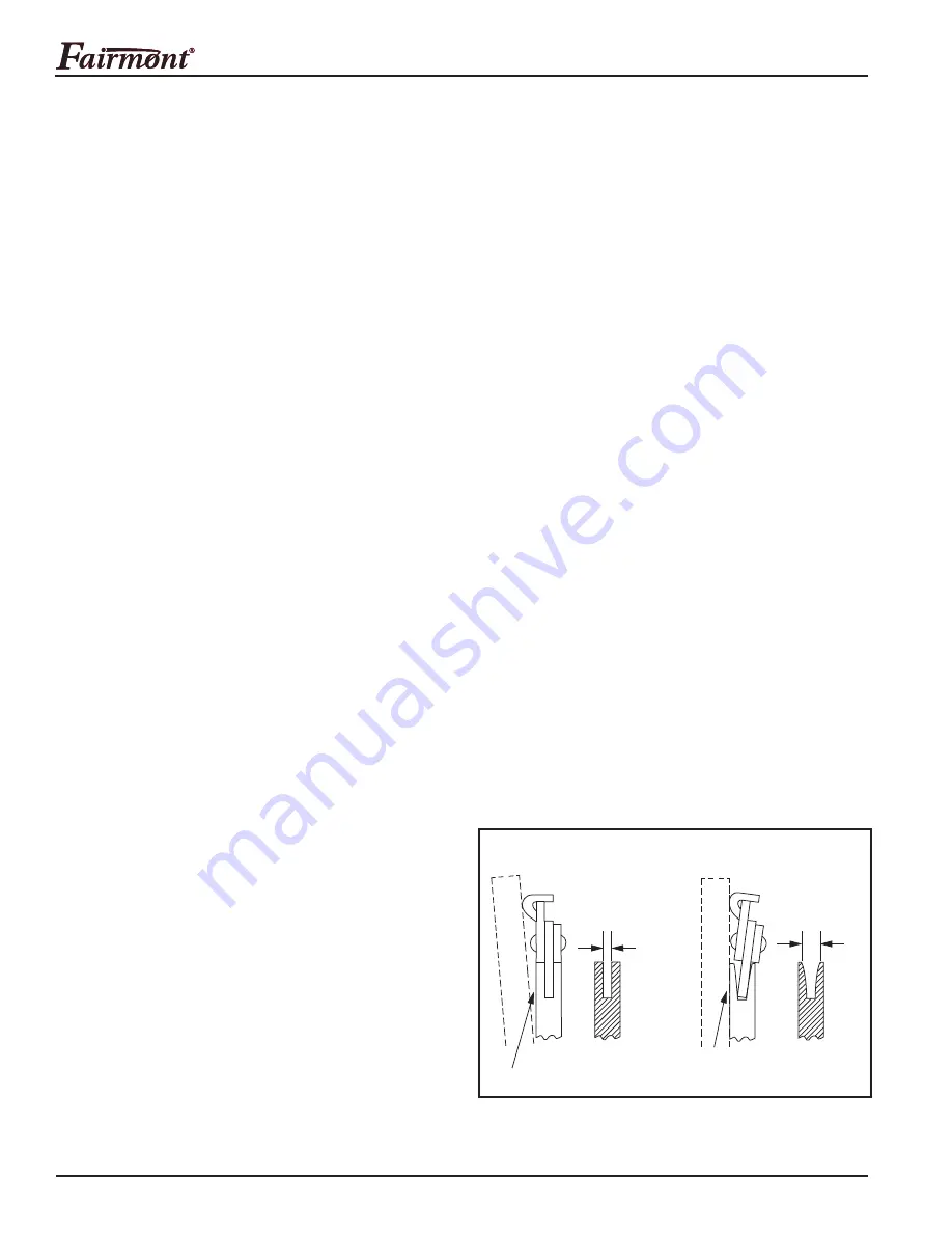
Check the bar rails for wear by placing a straight
edge against the side of the bar and one cutter.
Clearance between the bar and the straight edge
indicates that the bar rails are not worn.
If the chain leans and there is little or no clearance
between the bar and the straight edge, the bar
rails are worn and the bar should be replaced.
Checking the Rails for Wear
CHAIN IS STRAIGHT
Rails are
not worn.
Clearance
STRAIGHTEDGE
Rails are worn.
Replace bar.
CHAIN LEANS
No
Clearance
STRAIGHTEDGE
6. Inspect all other disassembled components for
cracks, grooves or nicks.
•
•


