background image

33

®

Model MSX Make-Up Air

Maintenance - Routine

CAUTION

Lock-out the gas and the electrical power to the 
unit before performing any maintenance or service 
operations to this unit.

V-Belt Drives

V-belt drives must be checked on a regular basis for 
wear, tension, alignment, and dirt accumulation.
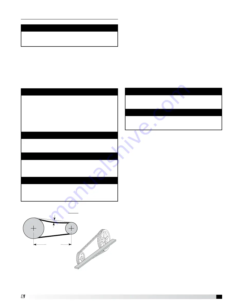
Check the tension by measuring the deflection in the 
belt as shown below.
Check the alignment by using a straight edge across 
both sheaves as shown below.

Snow Accumulation

Clear snow away from roof mounted units. Keep the 
snow clear of the intake and access doors.

Motors

Motor maintenance is generally limited to cleaning 
and lubrication (where applicable).
Cleaning should be limited to exterior surfaces only. 
Removing dust and grease build-up on the motor 
assures proper motor cooling.
Motors supplied with grease fittings should be 
greased in accordance with the manufacturer’s 
recommendations.

Wheels

Wheels require little attention when moving clean air. 
Occasionally oil and dust may accumulate on the wheel 
causing imbalance. When this occurs the wheel and 
housing should be cleaned to assure proper operation. 

Belt Tension

Belt Span

Deflection = Belt Span

64

FAN

MOTOR

FAN

MOTOR

Drive Alignment

IMPORTANT

Premature or frequent belt failures can be caused by 

improper belt tension, or misaligned sheaves.

•    Abnormally  high  belt  tension  or  drive 

misalignment will cause excessive bearing loads 

and may result in failure of the fan and/or motor 

bearings.

•    Abnormally  low  belt  tension  will  cause  squealing 

on start-up, excessive belt flutter, slippage, and 

overheated sheaves.

IMPORTANT

Do not pry belts on or off the sheave. Loosen belt 

tension until belts can be removed by simply lifting 

the belts off the sheaves.

IMPORTANT

When replacing V-belts on multiple groove drives, 

all belts should be changed to provide uniform drive 

loading.

IMPORTANT

Do not install new belts on worn sheaves. If the 

sheaves have grooves worn in them, they must be 

replaced before new belts are installed.

IMPORTANT

Do not allow water or solvents to enter the motor 

or bearings. Motors and bearings should never be 

sprayed with steam, water or solvents.

IMPORTANT

Greasing motors is only intended when fittings are 

provided. Many motors are permanently lubricated, 

requiring no additional lubrication.

Summary of Contents for MSX

Page 1: ... with this safety precaution could result in property damage serious injury or death WARNING Disconnect all electrical power to the fan and secure to the OFF position prior to inspection or servicing Failure to comply with this safety precaution could result in serious injury or death WARNING Improper installation adjustment alteration service or maintenance can cause property damage injury or dea...

Page 2: ...gs drive motor base and accessories for tightness 2 Rotate the fan wheel s by hand and assure no parts are rubbing Receiving Upon receiving the product check to make sure all items are accounted for by referencing the bill of lading to ensure all items were received Inspect each crate for shipping damage before accepting delivery Notify the carrier if any damage is noticed The carrier will make no...

Page 3: ... and less 42 inches 1066 8 mm on the controls side of the unit Housing 35 and higher 48 inches 1219 2 mm on the controls side of the unit Clearances for component removal such as evaporative cooler media may be greater than the service clearances listed Installation of Indoor Unit 3 Seal Wall Opening Apply sealant around the perimeter of the weatherhood to prevent water penetration and drafts into...

Page 4: ... and flash into place Attach the equipment support s to the roof remove metal cover flash to wooden nailer and reinstall cover 2 Install Ductwork Good duct practices should be followed for all ductwork All ductwork should be installed in accordance with SMACNA and AMCA guidelines NFPA 96 and all local codes Reference the CAPS submittal for ductwork sizes 3 Apply Sealant Apply an appropriate sealan...

Page 5: ...the supply unit will allow for easier installation of options 4 Apply Sealant Apply an appropriate sealant around the perimeter of the curb and duct adapter s to isolate fan vibration and prevent water penetration 3 Install Ductwork Good duct practices should be followed for all ductwork All ductwork should be installed in accordance with SMACNA and AMCA guidelines NFPA 96 and any local codes Refe...

Page 6: ...o the unit Detailed assembly instructions can be found with the weatherhood If the optional evaporative cooling module was selected this step does not apply refer to the next section Installation of the Optional Evaporative Cooling Module 9 Seal Weatherhood Seam Using an appropriate sealant seal the seam between the weatherhood and the unit NOTE The use of all lifting lugs and a set of spreader ba...

Page 7: ...e roof remove metal cover flash to wooden nailer and reinstall cover 4 Secure Cooling Module to Unit Use self tapping screws to fasten the cooling module to the base unit along the top and down both sides Fasten at the top through the flanges To fasten the sides the media must be removed To remove the media first remove the access panel on the evaporative module and disconnect the evaporative pump...

Page 8: ...in place of the remote switch The relay must be rated for at least 5 amps and have a 24 VAC coil Failure to comply with these guidelines may cause motor starters to chatter or not pull in resulting in contactor failures and or motor failures 1 Determine the Size of the Main Power Lines The unit s nameplate states the voltage and the unit s MCA The main power lines to the unit should be sized accor...

Page 9: ...al Electric Code NEC and The Space Heating Standard of the Underwriters Laboratories Inc UL Although UL requirements are uniform throughout the country local electrical codes may deviate from the National Electrical Code Therefore local inspection authorities should be consulted regarding local requirements Electrical Wiring Instructions 1 Use the wiring diagram supplied with the heater as a guide...

Page 10: ...vel should be above the pump intake and below the overflow Adjust the float as needed to achieve the proper water level Supply Line Overflow Trap Drain Line Valve Normally Open Drain Line Supply Line Valve Normally Closed Recirculating Evaporative Piping 6 in min 6 in min Drain Trap Evaporative Cooling with Auto Drain and Fill Auto Drain Flush Valves When provided by Greenheck Assembly Number GFC ...

Page 11: ...oid Valve B between the supply line and the drain line Refer to Auto Drain Fill Evaporative Piping drawing on previous page 2 Install the Drain Line Connect an unobstructed drain line to the sump drain overflow connection Install the 3 4 in normally open solenoid Valve C between the sump drain connection and the drain line A trap should be used to prevent sewer gas from being drawn into the unit 3...

Page 12: ...r Wizard only Additional instructions are provided for evaporative coolers equipped with the auto drain and fill or bleed off Warning Disconnect and lock out all power and gas before performing any maintenance or service to the unit Failure to do so could result in serious injury or death and damage to equipment Note Solenoid s may be provided by Greenheck if ordered or by others Caution Any wirin...

Page 13: ...re the vacuum in the piping using a micron gauge located as far from the pump as possible Evacuate the coil to 500 microns or less and then close the valve between the pump and the system If the vacuum holds to 500 microns or less 1 Locate the Distributor s by Removing the Distributor Access Panel Distributor Access Panel Installation of Direct Expansion DX Coil Piping optional Important Guideline...

Page 14: ...t pressurized for a minimum of 10 minutes If the coil holds the pressure the hook up can be considered leak free If the pressure drops by 5 psig or less re pressurize the coil and wait another 10 minutes If the pressure drops again there is likely one or more small leaks which should be located and repaired Pressure losses greater than 5 psig indicate a large leak that should be isolated and repai...

Page 15: ...ic gauge Run a second pressure tap line from the high pressure tap on the back of the photohelic gauge to the space Fifty feet of tubing is supplied with the unit 3 Set the Building Pressure The pressure gauge is used to set the desired building pressure The pressure is set by adjusting the knobs for the upper and lower pressure limits Typical settings are 0 0 inch wc for the lower and 0 10 inch w...

Page 16: ...phase units disconnect and lock out the power then interchange any two power leads Note To reverse the rotation on single phase units disconnect and lock out the power then rewire the motor per the manufacturer s instructions Important If the blower is rotating in the wrong direction the unit will move some air but will not perform as designed Be sure to perform a visual inspection to guarantee th...

Page 17: ...tion for adjusting information Note The most accurate way to measure the air volume is by using a pitot traverse method downstream of the blower Other methods can be used but should be proven and accurate Important Changing the air volume can significantly increase the motor s amps If the air volume is changed the motor s amps must be checked to prevent overloading the motor Note To ensure accurac...

Page 18: ...p Electric Heater optional warning Disconnect and lock out all power before performing any maintenance or service to the unit Failure to due so could result in serious injury or death and damage to equipment note If the heater is equipped with an optional inlet air sensor the heater will not energize unless the outdoor air temperature is less than the inlet air sensor s set point Refer to the Star...

Page 19: ...n 45 to 60 seconds Consult the factory if adequate flow is not achieved 6 Adjust the Water Bleed Off Rate The water bleed off rate is dependent on the water s mineral content The bleed off should be adjusted based on the media s mineral deposits after two weeks of service 7 Set the Optional Auto Drain and Fill Set the auto drain fill timer and temperature settings Timer settings are t1 1 0 10min t...

Page 20: ... Up and Down Keys to adjust the Minimum Cooling Temperature as needed Press the Enter Key to save the Minimum Cooling Temperature setting and return to the Program Menu 8 Exit Program Mode After 15 seconds of idle time the controller will exit Program Mode Minimum Cooling Temperature Display NOTE The enter key must be pressed to save the new minimum cooling temperature 5 Check Media Start the cool...

Page 21: ...Key for three seconds The display will read Pro when Program Mode is active 10 Adjust the Freeze Temperature While in Program Mode use the Up and Down Keys to navigate through the Menu Options until Frt is displayed Press the Enter Key to access the selected Menu Option setting Use the Up and Down Keys to adjust the Freeze Temperature setting as needed Press the Enter Key to set the Freeze Tempera...

Page 22: ...eps 1 5 should be performed before the blower is run NOTE For maintenance issues associated with variable frequency drives consult the drive s manual supplied with the unit The drives are programmed at the factory and should not need any adjustment during installation and start up For kitchen applications the drive may be located in the kitchen or in the unit Modulating Potentiometer Control a var...

Page 23: ...ALVES RECIRCULATION EXHAUST SUPPLY HEAT OPTIONAL 2 Position Damper Control 70 65 75 80 85 90 60 55 OPTIONAL BLOWER DIRTY FILTERS MAIN VALVES EXHAUST SUPPLY HEAT OPTIONAL GREENHECK With Maxitrol 44 Room Thermostat Potentiometer Control With Maxitrol 44 Room Thermostat 70 65 75 80 85 90 60 55 OPTIONAL BLOWER DIRTY FILTERS MAIN VALVES EXHAUST SUPPLY HEAT OPTIONAL GREENHECK PHOTOHELIC Building Pressur...

Page 24: ... starter ST1 N O contact on supply fan starter ST1 is energized and closed Supply fan M1 starts 3 Electric Heat Contact S4 Closed optional Power passes through N O contact on fan relay RF which is energized and closed Power passes through N C contact on optional inlet air sensor TS4 which is closed if the inlet air temperature is below the set point Power passes to and energizes heat relay RH Powe...

Page 25: ...out saving the change wait 10 seconds To exit Program Mode from the Program Menu wait 10 seconds Function Key L1 L2 L3 Enter Key Up Key Down Key Water Wizard User Interface Key Function Description Operation Water Wizard optional Caution The sump drain line must be clear and draining to a safe location before using Flow Test Mode Caution Be aware of the water level in the sump tank at all times wh...

Page 26: ...or fuse Replace One or more legs of 3 phase is out Restore missing legs 24 VAC across A2 and A1 on supply contactor ST1 24 VAC across terminals 4 and X 24 VAC across terminals 3 and X Supply Fan Overload ST1 OL tripped Reset and check motor amps Reference Blower Start Up 4 Optional Exhaust Fan Interlocks ST2 ST5 open Correct Replace Optional Damper Limit Switch DL1 holding Wait for actuator to ope...

Page 27: ...tor Motor voltage correct Provide proper power supply Reference Blower Start Up Step 1 Blower rotation correct Reverse blower rotation Reference Blower Start Up Step 2 Actual static pressure lower than design Adjust drives to reduce blower RPM Reference Blower Start Up Step 5 No No Yes Yes Yes Yes No Yes No No Shorted windings in motor Replace motor Yes Everything is working properly consult facto...

Page 28: ... Up Step 5 System static losses too high Reduce losses by improving ductwork Yes Yes Yes Yes No No No No No Leaks in ductwork Repair leaks Yes Belt slipping Replace or tighten belt Reference V Belt Maintenance in the Maintenance section Yes Everything is working properly consult factory Yes Too Much Airflow Blower speed too high Adjust drives as needed Reference Blower Start Up Step 5 Insufficient...

Page 29: ...lts worn or loose Replace worn belts or tighten loose belts Reference V Belt Drive Maintenance in the Maintenance section Yes Yes No No Yes Bearings worn or need lubrication Replace worn bearings or lubricate bearings as needed Reference Bearing Maintenance in the Maintenance section Yes No Wheel rubbing on inlet Adjust wheel s or inlet At this time noise and vibration should be at acceptable leve...

Page 30: ...f control loss Automatic and or Manual Reset Cutouts A and M tripped Reset Replace Automatic and or Manual Reset Cutouts A and M Check on cause of control loss 24 VAC between terminals T1 and 21 Heat Relay RH is not energized Check for loose connections Repair or replace Heat Relay RH 24 VAC between terminal A2 on heat relay RH and X Optional Inlet Air Sensor TS4 holding Adjust TS4 setting Referen...

Page 31: ... and located near the entering air side of the media Replace headers and or move the headers Reference Evaporative Cooler Start Up Step 1 Yes No Yes Yes No No 115 VAC between terminals 102 and 101 24 VAC between terminal A2 on Cooling Relay RC and X Cooling Transformer TR4 defective Replace transformer Optional Inlet Air Sensor TS4 holding Adjust TS4 setting Reference Blower Start Up Step 6 115 VA...

Page 32: ...e setting With the setting displayed use the Up and Down keys to adjust the setting as needed Increase the factor to increase the water supply or decrease the factor to decrease the water supply Press the Enter key to save the new On Time Factor and return to the Program Menu note If the water supply is too low the media will continuously appear dry note If the water supply is too high the media w...

Page 33: ...is occurs the wheel and housing should be cleaned to assure proper operation Belt Tension Belt Span Deflection Belt Span 64 FAN MOTOR FAN MOTOR Drive Alignment important Premature or frequent belt failures can be caused by improper belt tension or misaligned sheaves Abnormally high belt tension or drive misalignment will cause excessive bearing loads and may result in failure of the fan and or mot...

Page 34: ...s The bearings for Greenheck fans are carefully selected to match the maximum load and operating conditions of the specific class arrangement and fan size The instructions provided in this manual and those provided by the bearing manufacturer will minimize any bearing problems IMPORTANT Lubricate bearings prior to periods of extended shutdowns or storage and rotate shaft monthly to aid in corrosio...

Page 35: ...ng of the fluid If automatic air vents are not utilized periodic venting of the coil is recommended to remove accumulated air Cooling Coils Inspect the coil for signs of corrosion and or leaks Repair any leaks as required Inspect the coil s surface for foreign material If the coil surface needs cleaning clean the coil from the leaving air side so that foreign material will be washed out of the coi...

Page 36: ...nected to Open the drain valve or cap on the other header 5 Turn on blower for 30 minutes Place mirror at discharge If the mirror fogs up repeat procedure until no fog appears on the mirror 6 After drying the coil wait a few minutes then repeat Step 5 7 Leave drains open and do not install plugs until beginning of cooling season Flushing Coils Greenheck recommends the use of inhibited glycol such ...

Page 37: ...ntact for other equipment 10 Exhaust Fuses optional provides proper fusing for exhaust fan motor s 11 Exhaust Motor Starter optional 24 volt magnetic contacts for starting exhaust motor 12 Exhaust Overload optional provides electronic overload protection to exhaust motor 13 Inlet Air Sensor optional outdoor air stat that automatically controls the cooling based on outdoor air temperature 14 Coolin...

Page 38: ...heck for vibration o Supply fan RPM __________ RPM o Motor nameplate amps __________ Amps o Actual motor amps __________ Amps o Actual CFM delivered __________ CFM Optional Accessories refer to Blower Start Up section Step 6 for further detail o Heating Inlet Air Sensor _________ Actual Setting Typical setting 60º 70ºF 15º 21ºC o Cooling Inlet Air Sensor _________ Actual Setting Typical setting 75...

Page 39: ..._____________________ _________________________________________________ _________________________________________________ Date___________________ Time______________ AM PM Notes ___________________________________________ _________________________________________________ _________________________________________________ _________________________________________________ _____________________________...

Page 40: ...at www amca org Greenheck warrants this equipment to be free from defects in material and workmanship for a period of one year from the shipment date Any units or parts which prove defective during the warranty period will be replaced at our option when returned to our factory transportation prepaid Motors are warranted by the motor manufacturer for a period of one year Should motors furnished by ...

Reviews: