background image

8

Model GGH2O

®

NOTE

•  

 For multiple hood systems that have more than 
14 lights total (incandescent or fluorescent), the 
hood lights must be wired to multiple circuits. 
Each circuit must have less than 14 lights total.

•   Light bulbs are not provided. Standard light bulbs 

up to 100 watts may be used.

Double Island Style Hoods

A double island hood is created by installing two 
wall style hoods back to back. Use the installation 
procedure for single island hoods; install and level 
both hoods. After leveling, secure the hoods together 
by tack-welding and/or bolting the rear mounting 
brackets. Caulk this joint with NSF Approved silicone 
caulk (GE SCS1000 or its equivalent). The caulk is not 
provided.

Hood

Bolt

Caulk

U-Clip

Acorn Nut

Ho

od

 Fr

ont

Ho

od

 Fr

ont

1. Remove support angle on open end panel.
2. Raise all hoods into appropriate location and support per construction plans.
3. Fasten top angles together using 1/4 in. bolts and nuts (by others).
4. Fasten hoods together using u-clips, 1/4 inch bolts and cap nuts as indicated.
5. Caulk all seams as necessary.

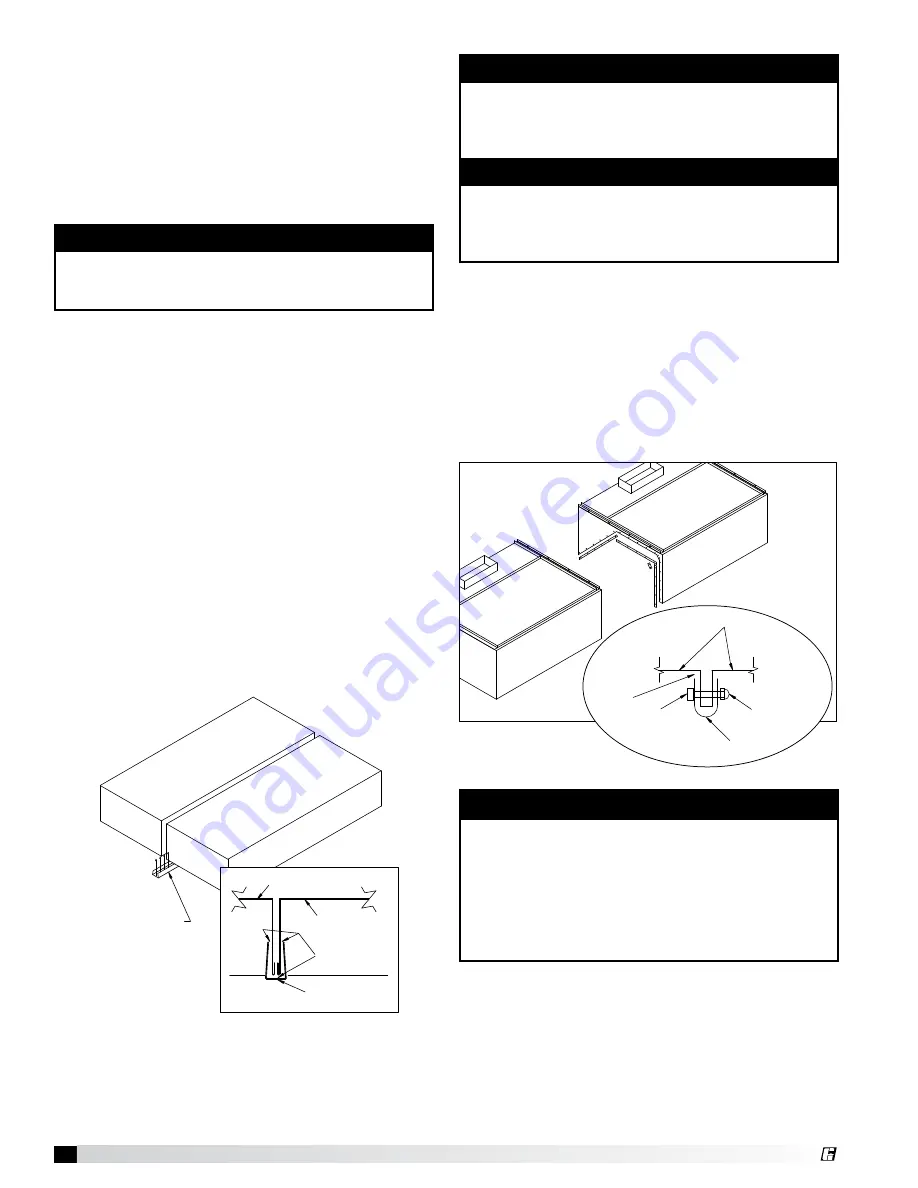
Continuous Capture Plenum Hoods

Remove the support angles on the open end panels. 
Use the installation procedure described for single 
island hoods; install and level both hoods. After 
leveling, secure the hoods together by tack-welding 
and/or bolting the top angles. Fasten the hoods 
together using u-clips and bolts. Caulk this joint with 
NSF Approved silicone caulk (GE SCS1000 or its 
equivalent). The caulk is not provided.

NOTE

Before hanging the hoods, please verify the hood 
marks to make sure the correct hood is hung on the 
correct side.

Installing U-Channel Strip

1.  After the hood is hung in position and leveled, 

apply caulk to the inside edge of the double island 
clip.

2.  Position and install the clip by tapping into 

position along clip (friction fit).

3.  Caulk edges to seal out grease and allow for ease 

of cleaning. Caulk with NSF Approved silicone 
caulk, GE SCS1000, or its equivalent. The caulk is 
not provided.

Hood Hanging Height

The hood hanging height is critical. Hanging the hood 
at the incorrect height may significantly reduce the 
ability for the hood to function properly and may be in 
violation of codes. The hood hanging height (typically, 
78 in. (198.12 cm) above the finished floor) is given on 
the UL label located on the inside of the hood on the 
end panel. The hood must be hung level to operate 
properly. 

NOTE

The installation of the canopy hoods shall be 
in accordance with NFPA 96 (latest edition), 
Standard for Ventilation Control & Fire Protection of 
Commercial Cooking Operations.

NOTE

Greenheck does not recommend walking or 
standing on the hood top as damage can result. If 
you must walk on the hood top, protect the hood 
with additional support or planks for flooring.

DETAIL A

Double Island Clip

Silicone Caulk

Hood-1A

Hood-1B

Installation Instructions.
1. After hood is hung in position and leveled…
2. Apply silicone caulk to inside of double island clip.
3. Position and install clip by tapping into position along clip (friction fit).
4. Caulk edges to seal out grease and allow for ease of cleaning.

Ho

od

-1B

Ho

od

-1A

Ho

od

 Fr

on

Double Island Clip

Summary of Contents for Grease Grabber GGH2O

Page 1: ... prevent accidental power up CAUTION When servicing the unit motor may be hot enough to cause pain or injury Allow motor to cool before servicing Installation Operation and Maintenance Manual Please read and save these instructions Read carefully before attempting to assemble install operate or maintain the product described Protect yourself and others by observing all safety information Failure t...

Page 2: ...y of each item have been received If any items are missing report shortages to your local representative to arrange for obtaining missing parts Sometimes it is not possible that all items for the unit be shipped together due to availability of transportation and truck space Confirmation of shipment s must be limited to only items on the bill of lading Handling Units are to be rigged and moved by t...

Page 3: ...atically engaged to run at the same time each day through a programmable timer Grease Grabber H2O System Function Table of Contents Grease Grabber H2O System Function 3 Cleaning Cycle Manual and Automatic Engagement 4 Fire Mode 4 System Components Hood 5 Grease Grabber H2O Control Cabinet 5 Graphic Keypad 5 Unpacking 6 Hood Widths and Base Weights 6 Installation Overview Filler Panels 7 Back Suppl...

Page 4: ...er and detergent will fill the hood reservoir The soapy water will then be cycled through the hood by the attached recirculation pump cleaning both the filter banks and the exhaust plenum area on a timed cycle When the cleaning cycle is complete the water is purged from the reservoir by the pump and the reservoir will again fill with clean hot water A rinse cycle will then run on a timed cycle and...

Page 5: ...ing CLEAN HOOD Fans will automatically stop 472620 In case of emergency the wash cycle can be stopped by pressing CLEAN HOOD CLEAN HOOD HOOD LIGHTS FAN ON OFF FAN 100 SYSTEM FAULT FILL DETERGENT After pressing CLEAN HOOD Fans will automatically stop In case of emergency the wash cycle can be stopped by pressing CLEAN HOOD CLEAN HOOD GGH2O and Melink Intelli Hood Keypad SETUP 100 Listed 33 x 7 LUCE...

Page 6: ...ion process 1 2 3 Profile of Hood Profile of Hood Profile of Hood Profile of Hood Remove side back and top lumber Remove 3 inch lag screws Holding the front lifting skid in place and position the skid in front of bottom skid Carefully rotate hood as shown Carefully slide the hood onto the lifting skid The lifting skid should be used to life the hood into it s final position If the lifting skid is ...

Page 7: ...or must be contacted at this time After the fire system has been installed mount the enclosures then the supply plenums If an Horizontal Supply Plenum is provided it should be installed before the enclosures The hood and accessories are now installed Finally make the electrical connections from the controls to the fans and complete the fire system circuits as required by the job specification job ...

Page 8: ... u clips and bolts Caulk this joint with NSF Approved silicone caulk GE SCS1000 or its equivalent The caulk is not provided NOTE Before hanging the hoods please verify the hood marks to make sure the correct hood is hung on the correct side Installing U Channel Strip 1 After the hood is hung in position and leveled apply caulk to the inside edge of the double island clip 2 Position and install the...

Page 9: ...tion instructions now Supply Supply ductwork where applicable should be connected to the hood in a manner approved by the local code authorities For proper installation of duct collars when they are shipped unattached see Installing Duct Collars on page 10 Hood UTILITY CABINET TOP VIEW HOOD TOP VIEW SUPPLY PLENUM SUPPLY PLENUM SHELL END VIEW HOOD FRONT Option 2 Uni Strut supplied by others Option ...

Page 10: ... in mm in mm ft m Back Supply 35 0 15 878 6 152 4 Variable Variable 3 to 16 91 to 4 88 145 cfm ft 246 36 m3 hr Air Curtain Supply 14 inch 9 5 4 31 14 355 6 10 254 3 to 16 91 to 4 88 110 cfm ft 186 89 m3 hr Air Curtain Supply 24 inch 12 5 5 67 24 609 6 10 254 3 to 16 91 to 4 88 145 cfm ft 246 36 m3 hr Variable Supply 16 0 7 26 12 304 8 18 457 20 3 to 16 91 to 4 88 curtain 0 80 cfm ft 0 135 92 m3 hr...

Page 11: ...GESTED LOCATION ABOVE CUT 1 4 in X 24 in OPENING AT CENTERED ON WIDTH OF THE SUPPLY IF MODULE 6 ft STEP 1 4 in TO 6 in FASTEN WITH S PLACE THE DU L MODULE LENGTH L 2 L 2 L 2 L MODULE LENGTH L 4 L 4 STEP 1 CENTERED ON WIDTH OF THE SUPPLY CUT 2 4 in X 24 in OPENINGS AT THE SUGGESTED LOCATIONS ABOVE IF MODULE 6 ft THE SUGGESTED LOCATION ABOVE CUT 1 4 in X 24 in OPENING AT CENTERED ON WIDTH OF THE SUP...

Page 12: ...R THE BACKSUPPLY IF IT WILL NOT INTERFERE 2 BEFORE THE HOOD IS HUNG THE BACKSUPPLY MUST BE SECURED INSTRUCTIONS AND THE FOLLOWING PROPERLY AS DESCRIBED IN STEP 3 in STEP 4 5 Connect the remaining ductwork for the back supply and the hood It is recommended that caulk be applied at the mating seams and surfaces of the back supply the hood and the wall Air Diffusers The air diffusers located at the b...

Page 13: ...t provided Note Installation instructions may not be applicable for concrete ceilings Installing End Skirts 1 After the hood is hung in position slide the hemmed form on top of the end skirt onto the end panels of the hood 2 Drill a hole in the hood end panel to line up with the hole in the end skirt Attach the end skirt with a 1 4 in bolt and cap nut to the inside of the hood or tack weld the end...

Page 14: ...E PIECES PANELS UP TO 48 IN 1219 2 MM WIDE SHIP IN ONE PIECE OVER 48 IN 1219 2 MM IN MULTIPLE PIECES Length 1 inch 25 4 mm Heigth Length Height 1 After the hood is hung in position slide the flat flange of the backsplash panel behind the back of the hood Note If the backsplash panel length is greater than 45 in 114 3 cm it will be shipped in multiple pieces 2 After the backsplash panel has been po...

Page 15: ...onnection Exhaust duct connection is to be a continuous liquid tight weld to hood Supply Duct Connection Supply duct connection to be tack welded with 1 to 2 inch tacks or sheet metal screws at 3 to 6 inch spacing to hood Front of Hood Exhaust Plenum 8 0 8 0 8 0 3 0 3 0 14 0 8 0 1 0 12 0 NOTE 1 Exhaust duct connection to be located within 48 inches from center of hood length to center of duct conn...

Page 16: ...d detergent is non caustic and biodegradable waste water from the hood can be drained in any typical grease trap A One inch unions B Detergent tank C Mounting plate D Isolators qty of four E Detergent pump Position pump on 4 isolators and attach using provided nuts Field connect 1 inch unions 1 inch female NPT Connect to drain Connect to control cabinet per Wiring Diagram in panel Once the hood is...

Page 17: ...eenheck for use in the wash system Use Formula G 510 full strength This product is biodegradable non caustic and safe for kitchen staff to use If G 510 detergent is not used the cleanliness of the exhaust plenum and filters cannot be guaranteed Preventative Maintenance The following practices will prolong the life of the detergent pump Keep detergent tank filled Avoid spilling detergent on the ext...

Page 18: ...sive order of time for example 8 00 pm ON 9 00 pm ON 10 00 pm ON Not 8 00 pm ON 10 00 pm ON 9 00 pm ON b Do not overlap event times for example 8 00 pm ON 12 00 pm OFF and 9 00 pm ON 11 00 pm OFF c Set the OFF time for one minute after the ON time Reviewing Events Programmed In your current time display press the PROG program button repeatedly to check your settings When finished press the CLOCK b...

Page 19: ...ose valve until water mist is no longer felt above equipment Once the valve is set it will not need to be moved again Verify the Grease Grabber H2O sequence of operation see the diagram of wash sequence on page 20 during the detergent pump cycle Daily Operation of the GGH2O Hood Pressing the FAN ON OFF button will start stop the exhaust and supply fans if interlocked Pressing the HOOD LIGHTS butto...

Page 20: ...t pump OFF Spray for 5 minutes Spray for 5 minutes 20 minute dry time Wash rinse dry complete No Temperature Interlock Exhaust Mode in Fire STOP Exhaust Mode in Fire RUN No Yes Shut OFF exhaust fan s Turn OFF exhaust fan s Stage 1 Fill hood tank hot water Stage 2 Wash primary filters Detergent pump ON Stage 3 Wash secondary filters Detergent pump ON Stage 5 Wash secondary filters Detergent pump OF...

Page 21: ... x 4 846 x Average inlet slot velocity x 2 47 144 Average Velocity Sum of Velocity Readings Number of Readings Hood Length 48 to 72 inches 72 to 120 inches 120 to 192 inches Minimum Number of Test Locations 3 5 7 For measuring exhaust airflow rates cubic feet per minute CFM use a short ridge meter to measure velocities along the inlet slot of the hood To ensure accurate data all appliances should ...

Page 22: ... MICROSWITCH IN NORMAL INSTALLATION THE YELLOW WIRE IS TO BE USED ONLY FOR EXTINGUISHER ALARM LIGHTS CIRCUITS ETC L1 L2 PUSHBUTTON SWITCH 120V 60HZ K1 Ka K1b CURRENT DRAW MAX 8A RESISTIVE 8A INDUCTIVE 120VAC NOTES 1 DENOTES FIELD INSTALLATION 2 DENOTES FACTORY INSTALLATION 3 GAS VALVE UL LISTED ELECTRICALLY OPERATED SAFETY VALVE FOR NATURAL OR LP GAS AS NEEDED OF APPROPRIATE PRESSURE AND TEMPERATU...

Page 23: ...N WITH ANSUL ANSUL SNAP ACTION SWITCH BLACK RED NEUTRAL HOT 1 L2 L NOTE ANSUL file name Typicalwiringschematicelectricequipmentshutdowndetail ai File received on August 4 2010 TEMPERATURE RATING 110V 60HZ OR ANSUL GAS VALVES PART NUMBERS 13707 13708 13709 13710 AND 17643 GAS VALVES UL LISTED ELECTRICALLY OPERATED SAFETY VALVE FOR NATURAL OR LP GAS AS NEEDED OF APPROPRIATE PRESSURE AND DO NOT USE B...

Page 24: ...BK RD 12 GA 12 GA 12 GA 18 GA 18 GA 18 GA 18 GA BK BK BK BK N WHT BL BL PR PR PR PR PR BR PR PR PR 18 GA YW YW YW 12 GA 18 GA PR PR R6 120 VAC Wash Timer Relay A1 A2 T1 T2 Timer Contact BK RD BK N WHT RD R6 Wash Timer 11 PR PR 5 10 13 11 1 6 2 3 15 14 N WHT 36 DI12 Safety FL3 F3 PR E2 14 GA 14 GA E1 2 AI1 4 AI COM TS TC OR BR 81 Earth 5 AI2 6 AI COM I1 IC OR BR Temp Sensor Freeze Protection If use...

Page 25: ...ling the filters Ensure no gaps are between filters after installation If any filter appears damaged consult factory for replacement Floats The floats need to be inspected two weeks after start up and then once a month thereafter The float can be inspected by first turning the disconnect switch on the control cabinet to the OFF position Then remove the large access panel door Once the access panel...

Page 26: ...aks water leaking through the access panels when filling Ensure access panels are securely in place If leak persists partially close inlet water ball valve by others upstream of fill solenoid to reduce water pressure Condensation in the hood large amounts of condensation while hood is washing Hood should be washed after the hood and equipment is warm not hot The warm equipment helps reduce the con...

Page 27: ... guide on page 26 Grease Grabber H2O Start Up Checklist Check boxes when item has been verified and gone over with customer Hook Up o Electrical Connected 120V 1 30A to terminals L1 and N for wash controls 120V 1 15A to terminals L2 and N1 for hood lights Fans to terminals E1 and E2 dry contact If using variable volume controls Melink will also require connection to terminals M1 and M2 Vari Flow w...

Page 28: ...__________________________ _________________________________________________ _________________________________________________ Date___________________ Time______________ AM PM Notes ___________________________________________ _________________________________________________ _________________________________________________ _________________________________________________ ________________________...

Reviews: