background image


www.GreenSeriesFitness.com


©April 2017 


Call Toll free at (800) 269-7130 

CIR-EL7000-G1      Revision 1.1 

John C. Jensen 

UNPACKING & ASSEMBLY 


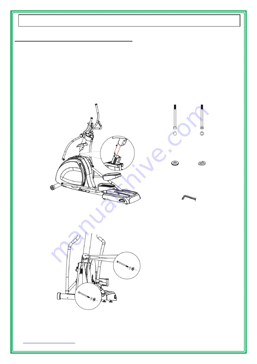
Step 4    Handlebar Set to Main Frame Assembly 


1.  With the help of a second person holding the Handlebar Set, connect the console wire, located at the bottom of 

the Handlebar Set, to the matting connector located at the top of the Main Frame. 

2.  Carefully pull the console wire through the Handlebar Set using the guide wire attached to the top of the 

Handlebar Set while lowering the Handlebar Set into the Main Frame receiving tube.   

Use caution while 

performing this operation as to not pinch or cut the console wire when lowering the Handlebar set onto 
the Main Frame

3.  Using a 6mm Allen wrench, insert the (2) M8x100 bolts, (2) M8x110mm, (4) M8 S washers and (4) flat washers 

into the Handlebar Set and matted Main Frame and tighten. 

4.  Lower and snap into place the Console Frame Cover onto the Main Frame.     


M

8

x1
1

0

m

m


M

8

x1
1

0

m

m


M8


M8

 S

 W
a

sh
e

X2


X2


X4


X4


Allen wrench 

(6mm)


M8x100mm 

M8x110mm 

#5-13 

#5-6 

#5-10

#5-21 

Summary of Contents for CIR-EL7000-G1

Page 1: ... Call Toll free at 800 269 7130 CIR EL7000 G1 Revision 1 1 John C Jensen Owner s Manual CIR EL7000 G1 Full Commercial Elliptical Install Date _________________________ Serial Number ________________________ Light Commercial Full Commercial ...

Page 2: ...rounding instructions how often you exercise how hard you exercise how long you exercise beginner treadmill program target heart rate zone TECHNICAL SPECIFICATIONS 5 UNPACKING ASSEMBLY 6 11 Parts hardware kit and assembly drawing WARM UP COOL DOWN 12 PANEL CONTROL 13 14 PROGRAM 15 PROGRAMS 16 20 OPERATION 21 CARE MAINTENANCE 22 PARTS LIST 23 24 EXPLODED DRAWINGS 25 27 WARRANTY 28 30 ...

Page 3: ...s are based on a combination of the ASTM U S voluntary standards and EN European regulations as of October 1 2012 for access passage around and emergency dismount ASTM standards are voluntary and may not reflect current industry standards The actual area for access passage around and emergency dismount is the responsibility of the facility The facility should consider the total space requirements ...

Page 4: ...out of use until repair This product is designed for adults Please ensure that children only use it under the supervision of an adult Make sure that all bolts and nuts are tightened when equipment is in use Periodic maintenance is required on all exercise equipment to keep it in good condition Close supervision is necessary when this equipment is used by on or near children invalids or disabled pe...

Page 5: ...ften you exercise You should exercise three to four times a week to improve your cardiovascular and muscle fitness How hard you exercise Intensity of exercise is reflected in your heart rate Exercise must be sufficiently rigorous to strengthen your heart muscle and condition your cardiovascular system Only your doctor can prescribe the target training heart range for you Before starting any exerci...

Page 6: ...rial number contains of ten values The location of the serial number shows as the figure SPECIFICATIONS Length 80 203 cm Width 27 68 cm Height 71 180 cm Weight of product 253lbs 115 2kg Program 9 programs 4 HRC Standard features 6 LED 8x32 dot matrix HR receive Resistance System Electromagnet Stride Length 20 50 cm Power source Built in generator rechargeable battery 12V 1 2AH ...

Page 7: ...Main Frame Console set Allen wrench 1pc 3mm Console frame cover PARTS 3 6 3 10 3 13 3 8 3 12 3 2 3 1 3 3 3 5 3 4 Allen wrench 1pc 5mm 5 3 5 7 5 5 5 11 5 12 Left cover right arm Right cover right arm Left cover left arm Right cover left arm 5 14 5 15 5 4 1pc 5 2 5 1 Step6 M4x12mm 8pcs Left right cover M3x30mm 2pcs Left right cover Allen wrench 1pc 6mm 1pc 1pc ...

Page 8: ...g carton carefully we suggest you to place a pad on the floor before you assemble the elliptical Moving and assembly of this product may require 2 or more persons Step 1 Move the Elliptical 1 Grab hold the rear of the elliptical and raise it up carefully Using the rollers on the front of the elliptical will provide an aid in moving the elliptical into the desired location ...

Page 9: ... ASSEMBLY Step 2 Assemble the Console Frame Cover 1 Slide the Console Frame Cover 5 5 onto the Handlebar Set 5 2 according to the illustration Step 3 Removal of the Pre lock Screws 1 Using a 6mm Allen wrench remove the 2 M8x100mm bolts 2 M8x110mm 4 8mm S washers and 4 flat washers located on the Main Frame 5 1 5 2 5 5 5 1 ...

Page 10: ...he Handlebar Set using the guide wire attached to the top of the Handlebar Set while lowering the Handlebar Set into the Main Frame receiving tube Use caution while performing this operation as to not pinch or cut the console wire when lowering the Handlebar set onto the Main Frame 3 Using a 6mm Allen wrench insert the 2 M8x100 bolts 2 M8x110mm 4 M8 S washers and 4 flat washers into the Handlebar ...

Page 11: ...e Handle Arm to the Pedal Linkage Step 6 Left Right Covers onto the Pedal Linkage 1 Assemble Right Left Arm Cover with Pedal Arm 2 You may push the Pedal Arm to the front of the Elliptical to make accessing and securing the covers easier 3 Fasten 4 M4x12mm screws on Left Right Arm Cover using a 5mm wrench 4 Fasten 1 M3x30mm screw on Left Right Arm Cover using a 3mm wrench M8x23 M8x16mm M8 Allen wr...

Page 12: ...11 John C Jensen UNPACKING ASSEMBLY Step 7 Console to Handlebar Set Assembly 1 Connect the Upper and Lower Console cables and the Hand Pulse cable 2 Connect the Lower Cable connector 3 Using a Phillips head screw driver secure the Console to the Handlebar Set with 4 M5x12mm screws M5x12mm 6 13 X4 ...

Page 13: ...them until they are over your head Reach your right arm as far upward toward the ceiling as you can for one count Feel the stretch up your right side Repeat this action with your left arm INNER THIGH STRETCH Sit with the soles of your feet together with your knees pointing outward Pull your feet as close into your groin as possible Gently push your knees toward the floor Hold for 15 seconds Repeat...

Page 14: ...www GreenSeriesFitness com April 2017 Call Toll free at 800 269 7130 CIR EL7000 G1 Revision 1 1 13 John C Jensen PANEL CONTROL Display Keys Message window display program profiles message ...

Page 15: ...rest Level Displays current resistance level L1 L25 Key function Key Function Adjusts the resistance level while in use Adjusts program types and program values Watts RPM Switch display Watts RPM Calories Mets Switch display Calories Mets Keypad Set value Enter Confirm value entered Quick Start Quick start or program start Reset Clear Clear the setting value while setting Reset back to idle mode w...

Page 16: ...al is set the program will not end unless manually stopped 2 Preset Programs 2 1 Press program key to select a preset program there are 7 preset program keys ROLLING VALLEY FAT BURN RAMP STRENGTH INTERVAL RANDOM 2 1 1 Message window show SET BODYWEIGHT THEN PRESS ENTER set body weight then press ENTER to next setting 2 1 2 Set time Message window show SET TIME THEN PRESS ENTER set time then press ...

Page 17: ...13 12 11 10 10 9 8 7 6 5 4 3 1 P3 LEVEL 1 1 1 3 3 3 5 5 5 6 7 7 8 8 9 9 10 LEVEL 2 1 1 5 5 5 7 7 7 8 9 9 10 10 11 11 12 LEVEL 3 1 2 5 6 6 7 8 8 9 10 10 11 12 12 13 13 LEVEL 4 2 3 6 6 7 8 9 9 10 10 10 11 12 12 13 14 LEVEL 5 3 4 7 7 8 8 9 9 10 10 11 12 12 13 14 15 P4 LEVEL 1 1 1 1 2 2 2 3 3 3 4 4 4 5 5 5 6 LEVEL 2 1 1 2 2 3 3 3 3 5 5 5 6 6 7 7 7 LEVEL 3 1 2 2 3 3 4 4 5 5 6 6 7 7 8 8 9 LEVEL 4 2 2 2 ...

Page 18: ...9 9 8 7 7 7 5 5 5 1 1 LEVEL 3 13 12 12 11 10 10 9 8 8 7 6 6 5 5 3 1 LEVEL 4 13 12 13 11 10 10 10 9 9 8 7 6 6 5 4 2 LEVEL 5 15 14 13 12 12 11 10 10 9 9 8 8 7 7 4 3 P4 LEVEL 1 6 7 7 7 8 8 8 8 6 5 4 4 3 2 1 1 LEVEL 2 8 8 9 9 10 10 11 11 11 9 9 8 8 7 7 6 LEVEL 3 9 9 10 10 10 11 12 13 12 11 9 9 8 8 7 7 LEVEL 4 9 9 10 11 12 13 13 14 14 12 10 9 9 8 8 7 LEVEL 5 10 10 11 12 13 14 15 15 14 14 13 12 10 10 9 ...

Page 19: ...S ENTER set age then press ENTER to next setting 3 2 2 2 Message window show SET BODYWEIGHT THEN PRESS ENTER set body weight then press ENTER to next setting 3 2 2 3 Set time Message window show SET TIME THEN PRESS ENTER set time then press ENTER to next setting 3 2 3 Set beginning Level Message window show SET BEGIN LEVEL THEN PRESS ENTER press or Key to set begin level press QUICK START to begin...

Page 20: ...0 3 minute the WATT preset value is 50W second begin watt depends on average heart rate of 2 3 minute of first stage show as below 4 4 2 The program will end when heart rate reaches MHR 85 10 over 10 seconds message window will show VO2 MAX XX press Reset Clear key back to idle mode PROGRAMS 2 01 3 00 Ave HR Stage 80bpm 80 89bpm 90 100bpm 100bpm 2 3 01 6 00 125W 100W 75W 50W 3 6 01 9 00 150W 125W ...

Page 21: ...t 800 269 7130 CIR EL7000 G1 Revision 1 1 20 John C Jensen Target Heart Rate Chart Please consult your physician to find your optimal heart rate and Watt setting MOVING OPERATION Increased Performance Range Aerobic Training Range Weight Loss Training Range ...

Page 22: ...eriesFitness com April 2017 Call Toll free at 800 269 7130 CIR EL7000 G1 Revision 1 1 21 John C Jensen Headphone jack and USB Port PREVENTATIVE MAINTENANCE USB For Workout Summary Data Saving and Software Updated ...

Page 23: ... on a regular basis NOTE Before use the elliptical please make sure the Aluminum tracks are cleaned and lubricated this is to prevent the damage and noise on tracks when you are exercising The exercise elliptical can be wiped clean with a soft cloth and mild detergent Do not use abrasives or solvents To prevent damage to the console keep liquids away from the console and keep the console out of di...

Page 24: ... H041007 000 Drive belt 1 1 4 9 F300256 005 Right housing cover K90 1 2 13 F900304 000 Shaft Secondary Shaft Assembly 1 4 10 F270220 000 Housing cover fixer 5 2 14 F300252 000 Pulley drive 1 4 11 H020803 001 Bolt M4x10mm 20 2 15 H041008 000 Drive belt 2 1 4 12 H020202 003 Bolt M4x12mm 2 2 16 F900264 000 Spindle 1 4 13 F270383 000 Rear grip cover plate left 1 2 17 H022102 004 Nut M10 1 4 14 F270384...

Page 25: ...mm K90 4 5 14 F300268 103 Left cover left armt K90 1 6 14 F916434 018 Overlay K90 1 5 15 F300422 103 Right cover left armt K90 1 6 15 F340062 000 Membrane 1 5 16 F916407 000 Handle Button UP 1 6 16 F916405 010 Stickers Left K90 1 5 17 F916407 001 Handle Button DOWN 1 6 17 F916405 009 Stickers Right K90 1 5 18 F340061 000 Handle Button Membrane 2 6 18 F373405 000 Heart Rate PCB 1 5 19 F080236 000 H...

Page 26: ...www GreenSeriesFitness com April 2017 Call Toll free at 800 269 7130 CIR EL7000 G1 Revision 1 1 25 John C Jensen EXPLODED DRAWING CONSOLE SET ...

Page 27: ...www GreenSeriesFitness com April 2017 Call Toll free at 800 269 7130 CIR EL7000 G1 Revision 1 1 26 John C Jensen EXPLODED DRAWING CONSOLE SET ...

Page 28: ...www GreenSeriesFitness com April 2017 Call Toll free at 800 269 7130 CIR EL7000 G1 Revision 1 1 27 John C Jensen ...

Page 29: ...s limited warranty extends only to the original purchaser and is non transferable Shipping fees incurred from returns for under warranty service in the warranty time line will be paid by GREEN SERIES All shipping fees both to and from GREEN SERIES following this warranty time line period must be paid by the customer All returns both during and following the warranty time line period must be affect...

Page 30: ... to normal use and or exposure consumables and cosmetic items including but not limited to the following grips seats paint scratches and labels 7 Travel costs associated with service more than 100 miles or two hours outside the service area of GREEN SERIES service technicians shall be the responsibility of the customer 8 Any and all shipping damages visible or hidden shall be the responsibility of...

Page 31: ... defective parts and will ship replacement parts to the location specified dependent on parts availability via UPS 3 GREEN SERIES will pay for shipping to and from the customer only within the time allocated under the warranty time line following the original product installation date Following this period all shipping fees for post warranty repairs are the sole responsibility of the customer The ...

Reviews: