SKYCHARGE MOBILE
POWERED BY GREEN MOTION AND PIPISTREL
TECHNICAL DOCUMENTATION
NON-CONTRACTUAL
PICTURES
Page 1: ...SKYCHARGE MOBILE POWERED BY GREEN MOTION AND PIPISTREL TECHNICAL DOCUMENTATION NON CONTRACTUAL PICTURES...
Page 2: ...4 USAGE OF THE STATION 10 4 1 Description of the trolley 10 4 2 Description of the station 10 4 3 Charging states 10 5 MAINTENANCE 14 5 1 Troubleshooting 14 5 2 Cleaning or replacing the filters 15 5...
Page 3: ...interface Ethernet cable 3G 4G Remote management Software management system eMobility Cockpit online ENVIRONMENTAL Operating temperature 25 C to 45 C Altitude Up to 2000 m 6500 ft Setting On rollers...
Page 4: ...evice Doepke RCCB DFS 4 040 4 0 03 A EV R Or Eaton 167897 FRCDM 40 4 03 G B 1 The Installer must define the types of Circuit breaker The circuit breakers at panel of 40 A overvalued in order to ensure...
Page 5: ...NICAL DOCUMENTATION Page 5 Circuit diagram Connection Diagram Figure 1 GB T 18487 1 2015 Schematic Diagram of DC Charging Extracted from AS6968 Rev A Figure 2 GB T 20234 3 2015 DC Charging Plug Extrac...
Page 6: ...main converter box can lead to electric shock hazards Please make sure to carefully read instructions In case of a doubt please immediately contact Green Motion support 3 1 Opening the SKYCHARGE Mobil...
Page 7: ...working under voltage shall be avoided The electrical cable must reach the terminal from the left The electrical cable and the communication cable can be introduced into the SKYCHARGE Mobile housing f...
Page 8: ...in Password admin01 The router requires a password change during the first start Please contact Green Motion SA support for the password 3G 4G Configuration Insert the SIM card in the SIM1 port Connec...
Page 9: ...appears it must be closed Go to the Network WAN menu Activate the WAN network and deactivate the other networks Press Save Apply o Authorize the management of the router from the WAN Only if in a priv...
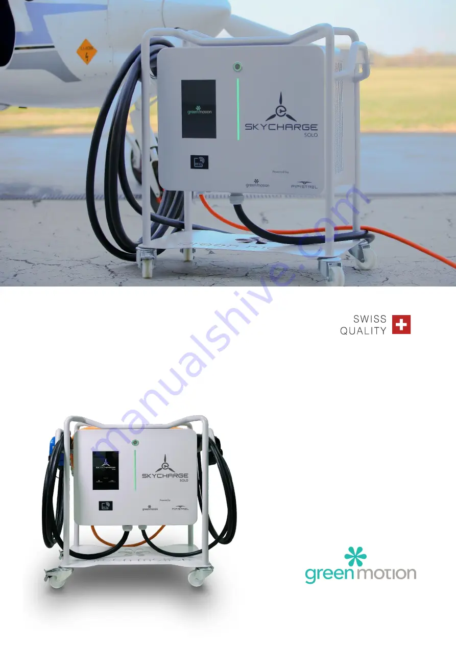
Page 10: ...1 Button indicator 2 Touch screen display 3 RFID reader 4 LED display 5 Emergency stop button To start a charge simply connect the plane via the GB T cable Then press on the screen to charge the plan...
Page 11: ...ging states Button indicator Button Status display Comments No light Not powered or start up stage Green light on Ready to be use or need user interaction Blue light on Charge initialization vehicle c...
Page 12: ...atus display Comments Green light on Ready to be use Flashing green light Start up stage Breathing green light Waiting for user interaction Flashing blue light Charge start up stage Breathing blue lig...
Page 13: ...e In this section you will find the information to start your experience LED Display status display Splash screen Touch the screen to wake up Authentication screen Before any operation please ensure t...
Page 14: ...ging station visual indicators are red Try to disconnect the plane from the charging station and retry Check the emergency button it should be pull out Antenna bar graph is red Check that the connecti...
Page 15: ...y In case of obstruction filters need to be replaced immediately Filters can be replaced They are accessible as described below Using a 2 5 mm hex key remove the 2 screws attaching each filter cartrid...