4
Modbus Gateway(Mini)
1 set
Owner’s Manual
5 Detailed Introduction of Modbus Gateway(Mini)
5.1
Interface
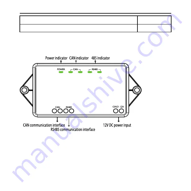
5.1.1
Interface Function Drawing
5.1.2
Power
The input power is 12V DC, external power supply can be prepared.
Page 1: ...Modbus Gateway Mini model ME30 24 E6 M ...
Page 2: ...y status for maintaining normal communication of system and preheating refrigerant and lubricant If the product is not to be used for long cut off the power supply please energize and preheat the unit in advance before reusing it 3 Please properly select the model according to actual using environment otherwise it may impact the using convenience 4 This product has gone through strict inspection a...
Page 3: ...nd after the error occurs 7 All the illustrations and information in the instruction manual are only for reference In order to make the product better we will continuously conduct improvement and innovation We have the right to make necessary revision to the product from time to time due to the reason of sales or production and reserve the right to revise the contents without further notice 8 The ...
Page 4: ...ay 6 5 3 DIP Switches 7 5 3 1 Setting of Address DIP Switch 7 5 3 2 Address DIP Switch S1 S2 Address Setting of Modbus Gateway 8 5 3 3 The Fourth Switch of Function DIP Switch S3 Setting of CAN2 Bus Matched Resistance 9 5 3 4 The Third Switch of Function DIP Switch S3 Setting of Modbus Bus Matched Resistance 10 5 3 5 The Second Switch of Function DIP Switch S3 Setting of gateway starting IDU proje...
Page 5: ...ion Space of Electric Control Cabinet 15 7 1 1 Product Dimension 15 7 1 2 Installation Dimension of Electric Control Cabinet 16 7 2 Communication Connection 17 7 2 1 Material Selection of Communication Cable 18 7 2 2 Communication Connection Way 18 7 2 3 Setting of Communication Connection 22 8 Annex DIP Address 25 ...
Page 6: ...talled at corrosive inflammable or explosive environment or the place with special requirements such as kitchen Otherwise it will affect the normal operation or shorten the service life of the unit or even cause fire hazard or serious injury As for above special places please adopt special product with anti corrosive or anti explosion function 2 User Notice Dear customer Please read this manual ca...
Page 7: ...amages to this device 7 Do install this device inside the electric control cabinet which is located indoor and then is locked 8 Do install this device where it will not be subject to the electromagnetic interference or heavy dust Notice 1 Be sure the specified adaptor is used otherwise this device would work improperly or even be damaged 2 Be sure this device is setup in place otherwise it would r...
Page 8: ... and snow etc 6 Graphics in the instruction manual are for reference only 3 General Functions Gree Modbus Gateway Mini is intended to realize the data exchange between the air conditioner and BMS and provides standard Modbus RTU protocol This gateway is applicable for DC Inverter GMV5 Water Source Heat Pump GMV5 GMV5 Mini GMV5 Slim and GMV5 Heat Recovery 4 Composition The product contains followin...
Page 9: ...ini 1 set Owner s Manual 1 set 5 Detailed Introduction of Modbus Gateway Mini 5 1 Interface 5 1 1 Interface Function Drawing 5 1 2 Power The input power is 12V DC external power supply can be prepared Modbus Gateway Mini ...
Page 10: ... power according to the interface instruction 5 1 3 Communication Interfaces CAN communication interface It is connected to air conditioner through two core connection wire to realize communication between Modbus Gateway Mini and air conditioner Modbus Gateway Mini ...
Page 11: ...eration status of each indicator is shown in the following table CAN TX When the data is transferred to the equipment e g air conditioner connected with Modbus Gateway Mini it will flash RX When the data from the equipment e g air conditioner connected with Modbus Gateway Mini is received it will flash RS485 TX When the data is transferred to the Modbus bus it will flash RX When the data from the ...
Page 12: ...ng DIP switches Otherwise this device cannot operate normally Setting area of Modbus gateway DIP switch is located inside the product including address DIP switch and function DIP switch 5 3 1 Setting of Address DIP Switch 1 Address DIP switch consists of S1 and S2 S3 is function DIP switch Modbus Gateway Mini ...
Page 13: ...sing this gateway The network DIP switch address of the same bus cannot be repeated otherwise communication error may happen Modbus Gateway Mini address setting range 1 255 Detailed DIP value please refer to the Address DIP Form Address setting example Setting method of address 11 is shown as below Modbus Gateway Mini ...
Page 14: ...atched Resistance Notice Notice Master outdoor unit or gateway of the system which is at the end of CAN2 bus must be set as with the matched resistance otherwise communication will be abnormal The fourth switch of function DIP switch is used for setting the CAN2 bus matched resistance of this gateway Modbus Gateway Mini ...
Page 15: ...o 1 DIP switch of matched resistance is shown as below n is ODU system quantity n 16 5 3 4 The Third Switch of Function DIP Switch S3 Setting of Modbus Bus Matched Resistance Notice The third switch of function DIP switch is used for setting the matched resistance of this gateway in Modbus bus Modbus bus Detailed meaning please refer to topology introduction The seventh switch of function DIP swit...
Page 16: ...d Switch of Function DIP Switch S3 Setting of gateway starting IDU project number Gateway starting IDU project number means the IDU range that this gateway can be handled The second switch of function DIP switch is used for setting the gateway starting IDU project number Gateway starting IDU project number is 1 this gateway can handle the IDU with project number from 1 128 Gateway starting IDU pro...
Page 17: ...ng Management System 6 1 Building Management System BMS This gateway adopts Modbus standard protocol which can be used as the interface of BMS It is applicable for DC Inverter GMV5 Water Source Heat Pump GMV5 GMV5 Mini GMV5 Slim and GMV5 Heat Recovery Modbus Gateway Mini ...
Page 18: ...13 6 2 Topological Graph 6 3 Topology Introduction Modbus bus L1 shown in the figure is the Modbus bus Modbus Gateway Mini ...
Page 19: ...can be connected to maximum 16 systems and 255 IDUs If the system quantity exceeds 16 sets or IDU quantity exceeds 255 sets it shall be divided into two CAN2 network L2 shown in the figure is CAN2 bus System One system consists of one set of outdoor unit one set of outdoor unit is a module group consisting of 1 4 modules that is 1 4 outdoor units and its connected indoor units Connectable unit qua...
Page 20: ...15 7 Product installation 7 1 Product Dimension and Installation Space of Electric Control Cabinet 7 1 1 Product Dimension Modbus Gateway Mini ...
Page 21: ...binet Modbus Gateway Mini shall be installed in the electric control cabinet The front side of gateway shall be hung upwards in horizontal level and secured by two screws Required installation space is shown as below only for reference Modbus Gateway Mini ...
Page 22: ...mmunication Connection Communication system of Modbus Gateway Mini includes 1 Communication between Modbus Gateway Mini and BMS 2 Communication between Modbus Gateway Mini and air conditioner Modbus Gateway Mini ...
Page 23: ... 75 IE C60227 5 2007 When communic ation distance exceeds 800m photoelect ric isolation repeater shall be added Communicati on between Modbus Gateway Mini and air conditioner Light Ordinary PVC sheathed twisted pair copper wire RVV L 500 2 0 75 IE C60227 5 2007 The length of communic ation cable shall not exceed 500m 7 2 2 Communication Connection Way Notice All communication cables of Modbus Gate...
Page 24: ...19 1 Communicaiton connection between Modbus Gateway Mini and BMS Modbus Gateway Mini ...
Page 25: ...20 2 Communication connection between Modbus Gateway Mini and air conditioner n is air conditioner quantity n 16 Modbus Gateway Mini ...
Page 26: ...21 Modbus Gateway Mini ...
Page 27: ...en Modbus Gateway Mini and BMS Step 1 Confirm the first Modbus Gateway Mini Modbus Gateway Mini 1 as shown in the figure that needs to be connected to BMS Connect the port of RS485 of this gateway and the BMS with communication cable as shown in step in the figure Modbus Gateway Mini ...
Page 28: ...onditioner and adopt series connection as shown in step in the figure Step 2 Connect the G1 and G2 port of CAN communication interface of Modbus Gateway Mini and the G1 and G2 port of wiring board of corresponding master ODU with communication cable as shown in step in the figure CAN2 network Detailed meaning please refer to topology introduction 3 Modbus Gateway Mini DIP setting Step one Set addr...
Page 29: ...matched resistance of Modbus Gateway Mini is introduced Meanwhile the master ODU in the first and end systems of CAN2 bus shall be set as with matched resistance In the following the detailed setting position and method of matched resistance of GMV5 DC inverter multi VRF are taken as example Modbus Gateway Mini ...
Page 30: ...ction 8 Annex DIP Address 0 31 DIP address table 32 63 DIP address table 1 2 3 4 a d dr 1 2 3 4 ad dr 0 0 0 0 0 0 0 0 0 0 0 0 0 1 0 0 32 1 0 0 0 0 0 0 0 1 1 0 0 0 0 1 0 0 33 0 1 0 0 0 0 0 0 2 0 1 0 0 0 1 0 0 34 Modbus Gateway Mini 1 2 3 4 1 2 3 4 1 2 S S 1 2 S S ...
Page 31: ...1 0 1 0 0 42 1 1 0 1 0 0 0 0 11 1 1 0 1 0 1 0 0 43 0 0 1 1 0 0 0 0 12 0 0 1 1 0 1 0 0 44 1 0 1 1 0 0 0 0 13 1 0 1 1 0 1 0 0 45 0 1 1 1 0 0 0 0 14 0 1 1 1 0 1 0 0 46 1 1 1 1 0 0 0 0 15 1 1 1 1 0 1 0 0 47 0 0 0 0 1 0 0 0 16 0 0 0 0 1 1 0 0 48 1 0 0 0 1 0 0 0 17 1 0 0 0 1 1 0 0 49 0 1 0 0 1 0 0 0 18 0 1 0 0 1 1 0 0 50 1 1 0 0 1 0 0 0 19 1 1 0 0 1 1 0 0 51 0 0 1 0 1 0 0 0 20 0 0 1 0 1 1 0 0 52 1 0 1 0...
Page 32: ...1 1 1 1 0 0 0 30 0 1 1 1 1 1 0 0 62 1 1 1 1 1 0 0 0 31 1 1 1 1 1 1 0 0 63 64 95 DIP address table 96 127 DIP address table 1 2 3 4 5 6 7 8 a d dr 1 2 3 4 5 6 7 8 ad dr 0 0 0 0 0 0 1 0 64 0 0 0 0 0 1 1 0 96 1 0 0 0 0 0 1 0 65 1 0 0 0 0 1 1 0 97 0 1 0 0 0 0 1 0 66 0 1 0 0 0 1 1 0 98 1 1 0 0 0 0 1 0 67 1 1 0 0 0 1 1 0 99 0 0 1 0 0 0 1 0 68 0 0 1 0 0 1 1 0 100 1 0 1 0 0 0 1 0 69 1 0 1 0 0 1 1 0 101 0 ...
Page 33: ... 1 0 1 1 0 110 1 1 1 1 0 0 1 0 79 1 1 1 1 0 1 1 0 111 0 0 0 0 1 0 1 0 80 0 0 0 0 1 1 1 0 112 1 0 0 0 1 0 1 0 81 1 0 0 0 1 1 1 0 113 0 1 0 0 1 0 1 0 82 0 1 0 0 1 1 1 0 114 1 1 0 0 1 0 1 0 83 1 1 0 0 1 1 1 0 115 0 0 1 0 1 0 1 0 84 0 0 1 0 1 1 1 0 116 1 0 1 0 1 0 1 0 85 1 0 1 0 1 1 1 0 117 0 1 1 0 1 0 1 0 86 0 1 1 0 1 1 1 0 118 1 1 1 0 1 0 1 0 87 1 1 1 0 1 1 1 0 119 0 0 0 1 1 0 1 0 88 0 0 0 1 1 1 1 0...
Page 34: ...0 0 1 0 1 160 1 0 0 0 0 0 0 1 129 1 0 0 0 0 1 0 1 161 0 1 0 0 0 0 0 1 130 0 1 0 0 0 1 0 1 162 1 1 0 0 0 0 0 1 131 1 1 0 0 0 1 0 1 163 0 0 1 0 0 0 0 1 132 0 0 1 0 0 1 0 1 164 1 0 1 0 0 0 0 1 133 1 0 1 0 0 1 0 1 165 0 1 1 0 0 0 0 1 134 0 1 1 0 0 1 0 1 166 1 1 1 0 0 0 0 1 135 1 1 1 0 0 1 0 1 167 0 0 0 1 0 0 0 1 136 0 0 0 1 0 1 0 1 168 1 0 0 1 0 0 0 1 137 1 0 0 1 0 1 0 1 169 0 1 0 1 0 0 0 1 138 0 1 0 ...
Page 35: ... 1 1 0 1 179 0 0 1 0 1 0 0 1 148 0 0 1 0 1 1 0 1 180 1 0 1 0 1 0 0 1 149 1 0 1 0 1 1 0 1 181 0 1 1 0 1 0 0 1 150 0 1 1 0 1 1 0 1 182 1 1 1 0 1 0 0 1 151 1 1 1 0 1 1 0 1 183 0 0 0 1 1 0 0 1 152 0 0 0 1 1 1 0 1 184 1 0 0 1 1 0 0 1 153 1 0 0 1 1 1 0 1 185 0 1 0 1 1 0 0 1 154 0 1 0 1 1 1 0 1 186 1 1 0 1 1 0 0 1 155 1 1 0 1 1 1 0 1 187 0 0 1 1 1 0 0 1 156 0 0 1 1 1 1 0 1 188 1 0 1 1 1 0 0 1 157 1 0 1 1...
Page 36: ... 0 0 1 1 197 1 0 1 0 0 1 1 1 229 0 1 1 0 0 0 1 1 198 0 1 1 0 0 1 1 1 230 1 1 1 0 0 0 1 1 199 1 1 1 0 0 1 1 1 231 0 0 0 1 0 0 1 1 200 0 0 0 1 0 1 1 1 232 1 0 0 1 0 0 1 1 201 1 0 0 1 0 1 1 1 233 0 1 0 1 0 0 1 1 202 0 1 0 1 0 1 1 1 234 1 1 0 1 0 0 1 1 203 1 1 0 1 0 1 1 1 235 0 0 1 1 0 0 1 1 204 0 0 1 1 0 1 1 1 236 1 0 1 1 0 0 1 1 205 1 0 1 1 0 1 1 1 237 0 1 1 1 0 0 1 1 206 0 1 1 1 0 1 1 1 238 1 1 1 1...
Page 37: ... 1 0 1 1 214 0 1 1 0 1 1 1 1 246 1 1 1 0 1 0 1 1 215 1 1 1 0 1 1 1 1 247 0 0 0 1 1 0 1 1 216 0 0 0 1 1 1 1 1 248 1 0 0 1 1 0 1 1 217 1 0 0 1 1 1 1 1 249 0 1 0 1 1 0 1 1 218 0 1 0 1 1 1 1 1 250 1 1 0 1 1 0 1 1 219 1 1 0 1 1 1 1 1 251 0 0 1 1 1 0 1 1 220 0 0 1 1 1 1 1 1 252 1 0 1 1 1 0 1 1 221 1 0 1 1 1 1 1 1 253 0 1 1 1 1 0 1 1 222 0 1 1 1 1 1 1 1 254 1 1 1 1 1 0 1 1 223 1 1 1 1 1 1 1 1 255 Modbus ...
Page 38: ......