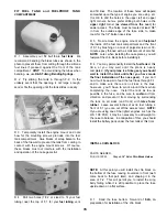
D 8 Mount the horns with 2-56 screws and the nylon
nutplates which were attached to the horns
2-56 x 5/8" Machine Screw
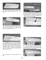
D 9. Screw a metal clevis onto the threaded end of
each long steel wire pushrod NOTE: Screw them
on all the way until the threads are protruding
inside the clevis.
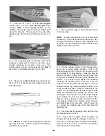
D 10 Cut the short length of 1/8" diameter plastic
tube (PLTB004) into several pieces, approximately
1/4" long Slide at least 8 of these pieces onto each of
the long pushrod wires and space them approximately
2-1/2" apart (do not glue yet) NOTE: If these tubes
do not slide on easily, cut them to a shorter length
NOTE: While installing the pushrods, position the
above plastic tube spacers so they always stay inside
the pushrod guide tubes If the tubes are not a tight
friction fit on the pushrod wires, apply a drop of thin
CA to secure them.
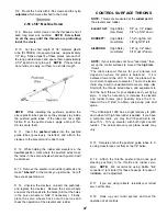
D 11. Insert the pushrod wires into the pushrod
guide tubes (previously installed) and attach the
clevises to the elevator and rudder horns.
CONTROL SURFACE THROWS
NOTE: Throws are measured at the widest part of
the elevator and rudder.
5/8" up 1/2" down
3/8" up 5/16" down
ELEVATOR*:
(High Rate)
(Low Rate)
(High Rate)
(Low Rate)
(High Rate)
(Low Rate)
1-1/2"+ right & left
7/8" nght7/8" left
RUDDER**:
1/2" up 1/2" down
5/16" up1/4"down
AILERONS:
NOTE: If your radio does not have "dual rates," then
set up the control surfaces to move at the high rate
throws
*The ideal elevator throws for your airplane will
depend on where the plane is balanced If it is
balanced toward the aft C G limit, the plane will be
much more responsive to elevator Too much elevator
throw may result in unwanted stalls or even snap rolls
Start with the throws listed above, and experiment to
find the best throws for your airplane and your flying
style It may be necessary to increase the elevator
and rudder throws (and possibly move the C G
toward the aft limit) to obtain crisp snap rolls and
spins.
**The Ultra-Sport 1000 has a slight tendency to pitch
down when full high rate rudder is applied If you have
a computer radio, you may find it beneficial to mix
about 5% - 10% up elevator with both right and left
rudder The actual amount your plane needs may
vary
D 12 While holding the rudder and elevators in the
neutral position, mark where the pushrod wires cross
the holes in the servo wheels where each pushrod will
be attached
D 13 Remove the elevator and rudder pushrods and
make "Z-bends" at the marks you just made. Cut off
the excess pushrod wire
D 14. Unscrew the clevises, re-insert the pushrods,
and replace the clevises Remove the servo wheels
and work the Z-bends into the holes (drill out the holes
in the servo wheels to 5/64' if necessary) Finally,
place the servo wheels back onto the servos and
check the operation of the elevator and rudder
D 15 Securely anchor the pushrod guide tubes to F-
4 using cross-braces cut from scrap 1/8" balsa
D 16 Attach the throttle pushrod (and nose gear
steering pushrod) to the throttle and rudder servo
arms NOTE: We recommend using DuBro "E-Z
connectors" (or similar) for these hookups, for ease of
installation and adjustment.
D 17 If you are using retracts, reinstall your retract
servo at this time
D 18 Hook up your radio system and test the
operation of all controls
47


