background image

3. The ideal power source for the Ryan STA EP is a 7-cell,
8.4 volt 1700 – 3000 mAh battery pack. The use of a higher
voltage battery may reduce the motor life and damage the
electronic speed control.

1. A new battery pack should be “cycled” for best results.You
should peak charge the battery, then discharge it almost
completely by actually running your motor with the propeller
attached. Do this 2 or 3 times on the ground before actually
flying. Be sure you remove the battery from the airplane
between each cycle and allow it and the motor to cool
before recharging.

2. The standard Tamiya battery connectors supplied with
your electronic speed control and motor battery are
adequate for most installations. However, if you are looking
for maximum performance, you may want to consider
installing high-performance battery connectors such as
DuraTrax

®

Powerpole

connectors (DTXC2300).

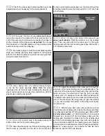
3. Examine your propeller for irregularities caused by the
injection molding process. Carefully remove the imperfections
with fine sandpaper.

Carefully balance your propeller and spare propellers before
you fly. An unbalanced prop can be the single most
significant cause of vibration that can damage your model.
Not only will motor mounting screws and bolts loosen,
possibly with disastrous effect, but vibration may also
damage your radio receiver and battery.

We use a Top Flite Precision Magnetic Prop Balancer

(TOPQ5700) in the workshop and keep a Great Planes
Fingertip Prop Balancer (GPMQ5000) in our flight box.

The best place to fly your Ryan STA EP is at an AMA
chartered club field. Ask the AMA or your local hobby shop

dealer it there is a club in your area and join. Club fields are
set up for R/C flying and that makes your outing safer and
more enjoyable. The AMA also can tell you the name of a
club in your area. We recommend that you join the AMA and
a local club so you can have a safe place to fly and have
insurance to cover you in case of a flying accident. The AMA
address and telephone number are in the front of this manual.

If a club and flying site are not available, find a large, grassy
area at least 6 miles away from houses, buildings and
streets and any other R/C radio operation like R/C boats
and R/C cars. A schoolyard may look inviting but is too close
to people, power lines and possible radio interference.

After you break-in the motor on the model, inspect the
model closely to make sure all screws remained tight, the
hinges are secure, the prop is secure and all pushrods and
connectors are secure.

Whenever you go to the flying field, check the operational
range of the radio before the first flight of the day. First,
make sure no one else is on your frequency (channel). Have
an assistant hold the model, staying clear of the prop. With
your transmitter on, you should be able to walk at least 100
feet away from the model and still have control. While you
work the controls, have your assistant tell you what the
control surfaces are doing. Repeat this test with the motor
running at various speeds. If the control surfaces are not
always responding correctly, do not fly! Find and correct the
problem first. Look for loose servo connections or corrosion,
loose bolts that may cause vibration, a defective on/off
switch, low battery voltage, a damaged receiver antenna, or
a receiver crystal that may have been damaged from a
previous crash. If the radio appears to only be affected when
the motor is running, try moving your receiver and receiver
antenna farther away from the motor battery and motor.
Recheck the C.G. Also, installing a couple more capacitors
on the motor may help. The capacitors should be soldered
from the terminals to the motor case, and from one terminal
to the other.

Use safety glasses when running the motor.

Do not run the motor in an area of loose gravel or sand; the
propeller may throw such material in your face or eyes.

Failure to follow these safety precautions may result in
severe injury to yourself and others.

MOTOR SAFETY PRECAUTIONS

Range Check

Ground Check

FIND A SAFE PLACE TO FLY

BALANCE THE  PROPELLER

PERFORMANCE TIPS

45

Summary of Contents for Ryan STA EP

Page 1: ...ing from the use by the user of the final user assembled product By the act of using the user assembled product the user accepts all resulting liability If the buyer is not prepared to accept the liab...

Page 2: ...eck 45 MOTOR SAFETY PRECAUTIONS 45 AMA SAFETY CODE excerpt 46 CHECK LIST 46 FLYING 46 Takeoff 47 Flight 47 Landing 47 TWO VIEW DRAWING BACK COVER FUSELAGE WING PLAN CENTER PULL OUT SECTION With its wh...

Page 3: ...re available at AMA club sites to help you get started the right way Contact the AMA at the address or toll free phone number below Academy of Model Aeronautics 5151 East Memorial Drive Muncie IN 4730...

Page 4: ...eter This method is only recommended for NiCd batteries Your charger may have sockets into which you may plug a voltmeter If not you may insert the probes from the voltmeter into the rear of the batte...

Page 5: ...ar sander GPMR6170 or similar Felt tip marker TOPQ2510 Rotary tool such as Dremel Moto Tool Rotary tool reinforced cut off wheel GPMR8020 Sealing iron TOPR2100 Curved tip Canopy Scissors for trimming...

Page 6: ...the same parts Not all die cut parts have a name or their complete name stamped on them so refer to the die drawings on page 7 for identification When it s time to remove the parts from their die she...

Page 7: ...7 DIE CUT PATTERNS...

Page 8: ...enter between the die cut LE and the trailing edge doubler Glue the stab center to the LE and to the front of the stab TE doubler 5 Pin the two die cut 3 16 4 8mm balsa stab frames S2 in position Glue...

Page 9: ...ncil to lightly mark the outline of the joiner wire on the elevators 7 Using a straightedge extend the sidelines of the elevator joiner outline forward to the leading edge Also use a Great Planes Prec...

Page 10: ...balsa stick cut and glue the fin ribs to the frame Note that one of the ribs is glued to the top edge of the fin base 4 Remove the fin from your building board Inspect all the glue joints and add CA t...

Page 11: ...y hinge slots if necessary so they all align Do not glue in the hinges until you are instructed to do so after the airplane is covered 1 Refer to the Expert Tip that follows and shape the leading edge...

Page 12: ...cut 3 32 2 4mm balsa wing rib W3 Make sure to make a left and right rib 3 Glue the die cut 3 32 2 4mm balsa rib doublers 3A to a W3 rib and a die cut 3 32 2 4mm balsa wing rib W4 Note on the wing plan...

Page 13: ...rs and the W3 and W4 ribs with the rib doublers The main spar will need to be bent upward to contact the W5 rib 10 Position the die cut 3 32 2 4mm balsa W1 root rib over the main spar Place the die cu...

Page 14: ...of ribs W1 through W3 Save the 3 4 19mm piece you cut off 15 Sand the balsa sub LE flush with the top of the ribs 16 Glue the die cut 3 32 2 4mm balsa rib doubler W1A to the inside forward edge of ri...

Page 15: ...od landing gear rail in half 24 Use epoxy to glue the landing gear rail in the notches centered between the W3 ribs 25 Use epoxy to glue the 3 8 x 3 4 x 3 4 9 5mm x 19mm x 19mm landing gear torque blo...

Page 16: ...ackups Glue the hinge backups to the front of the sub TE as shown on the wing plan 32 Glue the 1 4 x 3 4 x 30 6 4mm x 19mm x 762mm balsa leading edge centered on the front of the sub LE Trim and sand...

Page 17: ...wing plan 37 Return to step 2 and build the left wing panel 1 Draw centerlines along the width and the length of the two die cut 1 16 1 6mm plywood forward wing joiner and aft wing joiner 2 Using the...

Page 18: ...d to the bottom of the wing 7 Use epoxy to glue the wing bolt plate to the bottom of the wing The aft edge of the plate should be flush with the TE of the wing 8 Use a 3 16 4 8mm drill bit to enlarge...

Page 19: ...icks cut and glue aileron ribs to both sides of the aileron base perpendicular to the base 5 Trim the ends of the aileron LE and ribs flush with the aileron base 6 From the remaining 1 4 x 3 4 x 30 6...

Page 20: ...wing tip 15 Return to step 1 of Assemble the Ailerons and build the second aileron 1 Cover the fuselage plan with waxed paper or Great Planes Plan Protector When installing the formers make sure the e...

Page 21: ...the fuselage base Make sure the embossed F1A faces forward Note The front of the wing saddle will provide approximately 2 degrees of down thrust when the motor is installed 10 Glue the die cut 3 ply...

Page 22: ...alsa former F9 The stick is centered on the former and runs from the stab saddle slot to the bottom of the former 18 Glue the die cut 3 32 2 4mm balsa lower stabilizer saddle LSS to former F8A and F9...

Page 23: ...ith the formers 2 Trim a 1 16 x 3 x 30 1 6mm x 76 2mm x 762mm balsa sheet to fit between F1A and F6A Note Do not glue the forward lower sheeting to formers F6D which is glued behind F6A The sheeting s...

Page 24: ...tubes so that the ends are protruding 1 8 3 2mm in front of former F6A Glue the pushrod tubes to the formers and the lower sheeting The slots in the side of the fuse for the pushrod tube exit can be...

Page 25: ...sheeting Wetting the sheeting with water will allow the sheeting to bend around the tight radius at the aft end of the fuse 10 Trim and sand the upper fuselage sheeting flush with the face of formers...

Page 26: ...centered in the opening Glue the hatch pins to the hatch base and hatch pin doublers 9 Glue the die cut 3 32 2 4mm balsa backrest front BRF to the front of the back rest BR 10 With the battery hatch b...

Page 27: ...to the back rest 19 Sand the top of the sheeting and stringers flush with the top of the instrument panels Do not sand the sheeting on the backrest 20 Glue the remaining 1 8 x 3 3 2mm x 76 2mm sheetin...

Page 28: ...y align it with the fuselage 2 Use a tape measure to measure the distance from the corner of the aileron bay to the center of the tail Then measure the distance from the other aileron bay and check th...

Page 29: ...f the fuselage back to both stabilizer tips Adjust the stabilizer so that both measurements are the same The LE of the stabilizer should be against the back of former F8A With the wing mounted to the...

Page 30: ...ge 8 Cut the 3 4 x 2 1 2 x 6 19mm x 63 5mm x 152 4mm balsa block in half to make two rudder fairings Cut two pieces from the remaining piece of 3 16 x 3 8 balsa stick to make a dummy rudder to fit bet...

Page 31: ...o the side of the fin and the fuselage base 15 Mark the location of the tailgear wire on the rudder and the nylon tailgear bearing on the fuselage 16 Drill a 3 32 hole in the LE of the rudder at the m...

Page 32: ...ushrod in the rudder pushrod tube on the left side of the fuse Position the control horn on the rudder fairing and mark the control horn location on the fairing 6 Position a 3 ply control horn base ov...

Page 33: ...wo 4 x 3 8 9 5mm sheet metal screws Wrap two 64 rubber bands around the motor and motor mount 3 Use Velcro Hook and Loop material to mount the speed control on the side of the fuselage The material wi...

Page 34: ...Roughen the servo hatch where the epoxy will be applied Pack epoxy into the 1 16 1 6mm holes before clamping the blocks into position 2 After the epoxy has fully cured insert a 1 32 8mm temporary shim...

Page 35: ...metal screws 5 Return to step 1 of Mount the Landing Gear and install the main landing gear in the other wing half 1 Trim one matching set of wheel pant halves along the molded cut lines You can use a...

Page 36: ...strap and drill a 1 16 pilot hole at both marks 9 Drill a 1 8 hole in the center of the die cut 3 ply wheel pant retainer Slide the retainer over the landing gear Then securely attach the wheel pant t...

Page 37: ...mpound usually comes in small tubes dries quickly and sands easily but for proper drying can only be applied in thin layers 15 After the filler cures wet sand the wheel pants with 400 grit sandpaper t...

Page 38: ...a template to locate the cowl mounting blocks Reinstall the cowl and mark the location of the mounting blocks on the cowl Drill 1 16 pilot holes through the cowl and mounting blocks at each mark Atta...

Page 39: ...Top Flite MonoKote Hot Sock on your covering iron will prevent scratching the MonoKote film Before you cover the fuselage first apply 1 4 wide strips of white MonoKote film in the corners where the s...

Page 40: ...and watch it for a few days to be sure that you are satisfied with the end results 1 Cut the covering from the hinge slots in the elevator and stab Also cut the covering from the groove for the elevat...

Page 41: ...e you install the control surfaces TEMPORARY PIN TO KEEP HINGE CENTERED B Drill a 3 32 2 4mm hole 1 2 12 7mm deep in the center of each hinge slot A high speed Dremel Tool works best for this If you u...

Page 42: ...od 3 Carefully glue the windscreen in place with a canopy glue such as Pacer Formula 560 Canopy Glue PAAR3300 We do not recommend CA as it may fog the plastic Use masking tape to hold it in place whil...

Page 43: ...ry Use a Great Planes AccuThrow or a ruler to accurately measure and set the control throw of each control surface as indicated in the chart that follows If your radio does not have dual rates we reco...

Page 44: ...ne number and AMA number on or inside your model It is required at all AMA R C club flying sites and AMA sanctioned flying events Fill out the identification tag on the decal sheet and place it on or...

Page 45: ...of a flying accident The AMA address and telephone number are in the front of this manual If a club and flying site are not available find a large grassy area at least 6 miles away from houses buildi...

Page 46: ...ry and receiver are securely mounted in the fuse 3 Extend your receiver antenna and make sure it has a strain relief inside the fuselage to keep tension off the solder joint inside the receiver 4 Bala...

Page 47: ...altitude but maintain airspeed by keeping the nose down as you turn onto the crosswind leg Make your final turn toward the runway into the wind keeping the nose down to maintain airspeed and control...

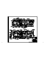
Page 48: ...TWO VIEW DRAWING Use copies of this page to plan your trim scheme...

Page 49: ...B C...

Page 50: ...D A...

Reviews: