background image

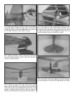
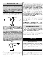
5. Turn on the transmitter and receiver. Double-check that

the elevator trim is centered and that the elevator is centered
to the stab. Mark the pushrod at the location that the elevator
pushrod crosses the hole in the control horn.

6. Cut the pushrod 1/2" [13mm] behind the mark on the

pushrod. Bend the pushrod 90 degrees away from the fuse.
Attach the pushrod to the middle hole of the control horn 
as shown.

7. Double-check that the rudder trim is centered and that

the rudder is centered on the fin. Mark the rudder pushrod
where it crosses the control horn.

8. Cut the pushrod 1/2" [13mm] behind the mark on the

pushrod. Bend the pushrod 90 degrees towards the top of
the fuse. Attach the pushrod to the control horn as shown.

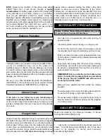
1. Following the motor manufacturer’s instructions,

assemble your motor and gear box.

2. The front of the motor mount is plywood. Temporarily

mount the gear box to the front of the motor mount with
three #2-3/8" [10mm] screws (included with the T280GD
ESC system). Remove the gear box from the motor mount.

3. Align the top, round shape of the motor mount to the

same shape in the former at the front of the fuse. Glue in place.

4. Using the mount’s top screw hole as a guide, drill a

3/16" [4.6mm] hole through the front of the fuse.

Note: The Headwind B is easily fitted with a variety of
powerplants. We tested the model most extensively with
the Great Planes T280GD ESC system with the 4.1:1 gear
ratio, and these instructions are written to install that
power system. We found that the GWS IPS IPS-DX2BB
motor system was also a good choice, and a motor mount
for the GWS system is included. Whatever motor you
decide to use, make sure to use one of the supplied motor
mounts so that the designed 2° of right thrust is built in.

Install the Motor

10

Summary of Contents for HeadWind "B"

Page 1: ...s all resulting liability If the buyer is not prepared to accept the liability associated with the use of this product the buyer is advised to return this kit immediately in new and unused condition t...

Page 2: ...roperty 2 You must assemble the model according to the instructions Do not alter or modify the model as doing so may result in an unsafe or unflyable model In a few cases the instructions may differ s...

Page 3: ...fast as NiCds Each individual cell that makes up a battery is 1 2 volts Simply stated a volt is the amount of power a battery pack can deliver a 6 cell battery pack is 7 2 volts Batteries are also ra...

Page 4: ...200 Here is a list of optional tools mentioned in the manual that will help you build the Headwind B Great Planes CG Machine GPMR2400 Straightedge with scale HCAR0475 Masking Tape TOPR8018 CA accelera...

Page 5: ...4 Tail Set GPMA2576 Landing Gear Set GPMA2578 Windshield GPMA2580 Hardware Pack ORDERING REPLACEMENT PARTS 5 1 2 3 4 10 9 7 8 6 1 Fuselage w windshield and outer pushrods 2 Horizontal tail 3 Vertical...

Page 6: ...ribs and pockets in the wing panels with a moderate but not excessive amount of 30 minute epoxy Join the wing halves together Ensure that the left wing remains flat and the right wing tip is 6 1 4 16...

Page 7: ...as shown 7 Glue the elevator control horn in place with medium CA Note The removed piece can be shaped and glued to the other side of the control horn for appearance if you desire but it is not neces...

Page 8: ...tab to the fuse Lift the stab off and coat the stab and fuse with epoxy Reinstall the stab with the pin for guidance Checking from behind the aircraft to make sure the stab is parallel with the wing e...

Page 9: ...sa sheet in the landing gear slot 1 Bend one end of both wire pushrods to the shape shown in the sketch 2 Slide the straight end of the pushrods into the fuselage through the front of the pushrod tube...

Page 10: ...mble your motor and gear box 2 The front of the motor mount is plywood Temporarily mount the gear box to the front of the motor mount with three 2 3 8 10mm screws included with the T280GD ESC system R...

Page 11: ...rsing in the transmitter to reverse the servos connected to those controls Be certain the control surfaces have remained centered Adjust if necessary Use a Great Planes AccuThrow or a ruler to accurat...

Page 12: ...ith the wing level have an assistant help you lift the model by the motor propeller shaft and the bottom of the fuse under the TE of the fin Do this several times 2 If one wing always drops when you l...

Page 13: ...this test with the motor running at various speeds with an assistant holding the model using hand signals to show you what is happening If the control surfaces do not respond correctly do not fly Fin...

Page 14: ...cking compound to secure critical fasteners such as the screws that hold the motor etc 7 Add a drop of oil to the axles so the wheels will turn freely 8 Make sure all surfaces are held securely in pla...

Page 15: ...toward the runway into the wind keeping the nose down to maintain airspeed and control Level the attitude when the model reaches the runway threshold modulating the throttle as necessary to maintain y...

Page 16: ...ook up an economical ElectriFly 4 Channel Mini FM receiver and it will automatically select the circuitry compatible with your Futaba JR Hitec or Airtronics Z radios Innovative circuitry makes them a...

Reviews: