


19
❏
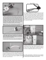
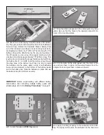
5. Fit the engine onto the mount and slide the engine mount
halves together against the engine crankcase. Remove the
engine and tighten the engine mount screws. Reposition the
engine onto the mount so that the front of the drive washer is
6-3/4" [171mm] from the fi rewall.
❏
6. Use a Great Planes Engine Hole Locator or a small drill
bit to mark the engine mounting holes into the engine mount.
❏
7. Drill 9/64" [3.6mm] holes at the marks you made and
thread the holes using a 8-32 tap and handle. Install the
engine onto the mount using four 8-32 x 1" [25mm] SHCS,
four #8 fl at washers and four #8 lock washers.
❏
8. Attach a Pitts-style muffl er to the engine.
Install the Fuel Tank (Glow Engine)
❏
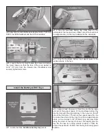
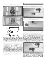
1. Locate the fuel tank. The hardware needed for the fuel
tank assembly is inside the tank. Remove the stopper and
shake out the contents.
❏
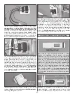
2. The fuel system for the Sukhoi SU-31 1.60 ARF utilizes
a three line system. There is a fi ll line, carb line, and
vent line (to muffl er). The fi ll line will allow fueling without
removing the cowl. The fi ll line is optional and may be omitted
if desired, or an optional Great Planes Easy Fueler
™
Valve
(not included) can be installed.
❏
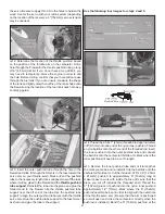
3. Use a hobby knife to open up the sealed third hole in
the rubber stopper. Slide the three aluminum fuel tubes into
the rubber stopper so that the tubes extend beyond the front
of the stopper by 1/2" [13mm]. If you are installing a fueler
valve or are omitting the fi ll line, install only two tubes into the
stopper (one short tube and one long tube) leaving the third
hole in the stopper sealed.
Summary of Contents for GPMA1412
Page 52: ......