GREAT PLANES Fokker D.VII ARF ElectriFly Instruction Manual Download Page 13

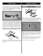
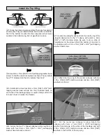
1. Study the above drawing carefully. There are four pairs of

strut mounts. They are labeled AC9a, AC9b, AC9c, and AC9d.
Test fit the bottom mounts into their respective strut mount
pockets in the bottom wing. Do not glue them in place.
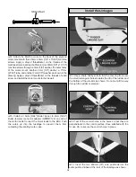
2. Use 2mm x 7mm [5/64" x 9/32"] self-tapping washer head

screws to hold the end struts in place as shown. The end struts
have “TF” stamped into them to indicate “Top Front.”
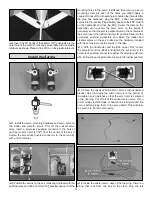
3. Install and remove four 2mm x 7mm [5/64" x 9/32"] self-

tapping washer head screws into the pre-drilled holes on
each side of the fuselage. Apply a couple of drops of thin CA
into each hole to harden the threads.

4. Locate the two “V” shaped cabanes and screw them in

place with four 2mm x 7mm [5/64" x 9/32"] self-tapping
washer head screws as shown.
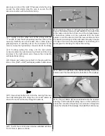
5. Locate two straight cabane struts. Secure the top of the

straight cabane strut to the “V” cabane with a 2mm x 6mm
[5/64" x 7/32"] machine screw. Be sure to use a drop of
threadlocker on the screw. Attach the bottom of the strut to
the fuselage with a 2mm x 7mm [5/64" x 9/32"] self-tapping
washer head screw.

6. Attach the top wing to the center cabanes with two

2-56 x 9.5mm [3/8"] machine screws and two 2mm [5/64"]
washers as shown.

7. Put the center rear cabanes in place. Attach the

cabanes with 2mm x 7mm [5/64" x 9/32"] self-tapping
washer head screws at the sides of the fuselage and with
2-56 x 9.5mm [3/8"] machine screws and two 2mm [5/64"]
washers in the bottom of the top wing.

Install the Top Wing

13

Summary of Contents for Fokker D.VII ARF ElectriFly

Page 1: ...used condition to the place of purchase To make a warranty claim send the defective part or item to Hobby Services at the address below Hobby Services 3002 N Apollo Dr Suite 1 Champaign IL 61822 USA I...

Page 2: ...nes link and select the Fokker D VII EP ARF If there is new technical information or changes to this model a tech notice box will appear in the upper left corner of the page We urge you to join the AM...

Page 3: ...required to finish the Fokker D VII EP ARF Order numbers are provided in parentheses 4 Channel radio with four micro servos with a minimum 17 oz in each such as the Futaba S3107 FUTM0025 1 ElectriFly...

Page 4: ...ist that follows The fastest most economical service can be provided by your hobby dealer or mail order company To locate a hobby dealer visit the Hobbico web site at www hobbico com Choose Where to B...

Page 5: ...at Planes Product Support 3002 N Apollo Drive Suite 1 Champaign IL 61822 Telephone 217 398 8970 ext 5 Fax 217 398 7721 E mail airsupport greatplanes com KIT INSPECTION 1 Battery Cover 2 Fuselage 3 Sta...

Page 6: ...DO NOT OVER SHRINK THE COVERING OR IT WILL CAUSE THE CONTROL SURFACES TO TWIST 3 Check the hinge slots of all control surfaces using a hobby knife with a 11 blade This will help when installing the hi...

Page 7: ...Place the stabilizer onto the stabilizer saddle 3 Stick a T pin into the center of the top of the firewall Tie a small loop in one end of a 900mm 35 piece of non elastic string such as K S 801 Kevlar...

Page 8: ...the aft end of the fuselage 10 Use a fine point felt tip pen to mark the outline of the fin on the top of the stabilizer 11 Remove the fin from the stabilizer Using the same technique used for the st...

Page 9: ...ommend that you start charging it now so you do not have to wait for it to charge later Make sure to closely follow the charging instructions for charging LiPo batteries We also recommend that you rem...

Page 10: ...let male to 2mm 5 64 Bullet female connector adapter GPMM3122 on each of the motor leads Connect the motor leads to the ESC Push the wires up into the fuselage to prevent them from contacting the rota...

Page 11: ...hen the ESC Center the trims on the transmitter and re center the servo arms on the servos if necessary so that the arm is perpendicular to the centerline of the servo Insert the rudder and elevator p...

Page 12: ...he small rectangular hole along the LE of each aileron as shown Do not cut all the way through the ailerons 11 Test fit the control horns and when satisfied with their fit CA them in place as shown 12...

Page 13: ...te the two V shaped cabanes and screw them in place with four 2mm x 7mm 5 64 x 9 32 self tapping washer head screws as shown 5 Locate two straight cabane struts Secure the top of the straight cabane s...

Page 14: ...e install the 2mm x 7mm 5 64 x 9 32 self tapping washer head screw 10 Use CA to glue one ABS side vent on each side of the fuselage as shown 1 Locate the radio compartment cover and secure it to the f...

Page 15: ...or shaft is centered in the opening Drill two 1 6mm 1 16 holes through each side of the cowl as shown Install and then remove a 2mm x 7mm 5 64 x 9 32 self tapping washer head screw into each of the ho...

Page 16: ...e motor battery to the ESC Move the throttle stick down to the off position Switch on the ESC and center the trims 2 Make certain that the control surfaces respond in the correct direction as shown in...

Page 17: ...has been installed 1 With the wing level lift the model by the prop shaft and the bottom of the fuse under the TE of the fin Do this several times 2 If one wing always drops when you lift the model i...

Page 18: ...surfaces are doing Repeat this test with the motor running at various speeds with an assistant holding the model using hand signals to show you what is happening If the control surfaces do not respond...

Page 19: ...der no circumstances may a pilot or other person touch a powered model in flight nor should any part of the model other than the landing gear intentionally touch the ground except while landing 1 Chec...

Page 20: ...crosswind leg Make your final turn toward the runway into the wind keeping the nose down to maintain airspeed and control Level the attitude when the model reaches the runway threshold At this point...

Reviews: