GREAT PLANES fairchild PT-19 Instruction Manual Download Page 22

22

fi ngertips. As long as the model balances anywhere within 
the specifi ed range it is acceptable (but less-experienced 

pilots should perform fi rst fl ights with the PT-19 balanced in 
the middle or forward half of the range—slightly nose heavy).

 3. If the PT-19 doesn’t balance where specifi ed, move the 

receiver battery or motor battery or add stick-on lead ballast 
to the nose or tail to achieve the correct C.G.

 4. If you’ve made any adjustments by adding ballast or 

moving components, check the C.G. again before fl ying.

Balance the Model Laterally

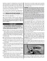
 1. Lift the PT-19 several times by the propeller shaft and 

the tail to see if one wing drops.

 2. If one wing drops consistently, add weight to the 

opposite tip by sticking it to the outside or strategically 
concealing it inside the balsa tip. 

An  airplane  that  has 

been laterally balanced will track better in fl ight and 
maintain its heading better during maneuvers when the 
plane is climbing.

PREFLIGHT

Engine/Motor Safety Precautions

Failure to follow these safety precautions may result 
in severe injury to yourself and others.

  Keep all engine fuel in a safe place, away from high heat, 

sparks or fl ames, as fuel is very fl ammable. Do not smoke 
near the engine or fuel; and remember that engine exhaust 
gives off a great deal of deadly carbon monoxide. Therefore


do not run the engine in a closed room or garage

.

  Get help from an experienced pilot when learning to 

operate engines.

  Use safety glasses when starting or running engines.

  Do not run the engine in an area of loose gravel or sand; 

the propeller may throw such material in your face or eyes.

  Keep your face and body as well as all spectators away 

from the plane of rotation of the propeller as you start and 
run the engine.

  Keep these items away from the prop: loose clothing, shirt 

sleeves, ties, scarfs, long hair or loose objects such as 
pencils or screwdrivers that may fall out of shirt or jacket 
pockets into the prop.

  Use a “chicken stick” or electric starter to start the engine. 

Do not use your fi ngers to fl ip the propeller. Make certain 
the glow plug clip or connector is secure so that it will not 
pop off or otherwise get into the running propeller.

  Make all engine adjustments from behind the rotating 

propeller.

  The engine gets hot! Do not touch it during or right after 

operation. Make sure fuel lines are in good condition so 
fuel will not leak onto a hot engine, causing a fi re.

  To stop a glow engine, cut off the fuel supply by closing 

off the fuel line or following the engine manufacturer’s 
recommendations. Do not use hands, fi ngers or any other 

body part to try to stop the engine. To stop a gasoline 
powered engine an on/off switch should be connected to 
the engine coil. Do not throw anything into the propeller 
of a running engine.

WARNING:


For brushless electric motors, never have the 

motor battery connected to the ESC without the transmitter 
turned on – after each fl ight (or any time after running the 
motor) 

always

 disconnect the battery 

before

 turning off 

the transmitter. And when ready to fl y (or whenever running 
the motor for any reason), always turn on the transmitter 
fi rst before connecting the motor battery.

Also make certain your 

failsafe

 is programmed correctly 

so in the event the receiver ever loses signal (or, if you 
inadvertently turn off the transmitter before disconnecting 
the battery or vice-versa) the motor will not turn. Follow 
the instructions that came with your radio control system 
to check and set the failsafe.

The recommended RimFire .32 is rated for 50A constant 

current and 80A surge current, so it is desirable to load 
(prop) the motor to operate within that range. The closer to 
50A the longer you can fl y full-throttle and the closer to 80A 
the less you can fl y full-throttle until the motor gets too hot.

To begin, an APC 13 x 8E (on a 4S LiPo) draws about 58A 

static and momentary, maximum peaks of about 50–55A 
in the air, but averages a little less than 20A with “normal” 
throttle use. This is a suitable propeller choice and fl ies the 
PT-19 well—it can be zoomed around boreing holes in the sky, 
or cruise at lower throttle settings for more scale-appearing 

fl ight and extended air time.

We’ve also fl own the PT-19 with a 13 x 10E on 4S which 

peps it up noticeably. Then, the static current rises to about 
68A with momentary, maximum in-fl ight peaks up to around 

70A and averages around 50A with normal throttle use. The 
13 x 10E is another suitable propeller, but 

prudent throttle 

management

 must be used so as not to overheat the motor 

and if necessary, it may be a good idea to allow the motor 
to cool between fl ights.

With every propeller, fl ight time depends greatly on how you 

use the throttle. Average current draw can be as low as 13 

Amps up to as high as 50 Amps if you’re REALLY hard on 

the throttle.

In any case, use a fl ight timer initially set to a conservative 
time (4 minutes for example). When the timer sounds, land. 
Resting (unloaded) voltage should not be below 3.75V/cell 

Summary of Contents for fairchild PT-19

Page 1: ...umed nor accepted for any damage resulting from the use by the user of the final user assembled product By the act of using the user assembled product the user accepts all resulting liability If the b...

Page 2: ...300mm universal servo extensions TACM2130 If mixing the aileron servos electronically with programmable mixing in the transmitter 2 6 150mm universal servo extensions TACM2092 If connecting the servo...

Page 3: ...arger capable of at least 70 Watts is required 4S x 4 2V cell 16 8V x 4A 67 Watts The Triton EQ2 GPMM3156 is more than enough charger with 100W output AC and 120W output DC Adhesives Hardware and Othe...

Page 4: ...instructions below to tighten the covering on your model 1 Stack two or three paper towel squares on top of each other and cut them into small squares During various stages of assembly these squares m...

Page 5: ...ary to any loose hinges Residual CA or CA fog is removable with a paper towel square dampened with CA debonder 4 If powering your PT 19 with a glow engine apply a film of epoxy or CA to edges of the c...

Page 6: ...ileron horns remove the screws harden the holes with a few drops of thin CA allow to harden and then reinstall the screws 8 Hook up the aileron servo in the right wing the same way It will be a little...

Page 7: ...gether and wipe away excess epoxy as it squeezes out Proceed quickly to the next step 5 Use a small clamp to clamp the front of the wing together at the tab and plenty of masking tape to tightly clamp...

Page 8: ...s Zap Goo It takes the Zap Goo approximately overnight to dry 3 Mount the wheels to the gear with a 4mm collar on both sides of each wheel held in place with an M3 set screw and threadlocker ASSEMBLE...

Page 9: ...15mm 5 Test fit the CA hinge and the tail gear into the rudder 6 Test fit stab and fin with CA hinge and tail gear into the fuselage View the model from behind Check the alignment of the stab to the w...

Page 10: ...the three holes in the tail gear bracket with a 3 32 2 4mm drill Position the bracket centered on the bottom of the fuselage Use the holes in the bracket to drill 1 16 1 6mm holes into the fuselage T...

Page 11: ...the ESC to the bottom of the motor mount box for the Castle Creations Edge Lite 75 ESC we soldered the female bullet connectors that came with the motor to the three motor wires protected with 3 16 he...

Page 12: ...all four engine mount holes on the circle embossed in the firewall so your engine and mount will be positioned properly 2 Press 6 32 blind nuts into the holes in the back of the firewall 3 Cut the sp...

Page 13: ...pushrod as necessary to connect to the servo arm and the carburetor arm with the hardware shown 4 A lite ply U brace is included for stabilizing the end of the throttle pushrod guide tube Cut the bra...

Page 14: ...ter the cowl has been cut and fitted Fit the Cowl Over the Engine If you ve installed a brushless motor the cowl probably requires no cutting so skip ahead to Mount the Cowl Cutting a cowl to fit over...

Page 15: ...e cowl from going on 3 Use your Dremel to cut the first hole at your mark Test fit the cowl Use a felt tip pen to mark the outside of the cowl where more trimming is required Residual ink can be wiped...

Page 16: ...former 4 Drill 1 16 1 6mm holes through the marks in the cowl into the fuselage sides As you drill each hole partially thread in a M2 5 x 10 washer head Phillips wood screw through the cowl into the h...

Page 17: ...ontacts the cowl ring this won t be the final glue job just enough to tack the cowl to the cowl ring You won t be able to reach the part of the cowl ring in the upper left hand corner but that can be...

Page 18: ...h the bottom of the fuselage MUFFLER INSTALLATION TIP When fitting the muffler and muffler extension OSMG2578 lay the model on its side so the muffler screws and extension won t fall off the engine On...

Page 19: ...d a few drops of thin CA into the holes allow to harden then mount the horn again 3 Align the clevis holes in the elevator horn with the hinge line then drill the holes for the elevator horn Mount the...

Page 20: ...ttery if used with straps made from more hook and loop material Also mount the receiver switch if used Scale Details 1 Use the lite ply pilot mount doubler to mark and drill holes in the cockpit floor...

Page 21: ...8 1 1 2 38mm 20 1 25mm 14 RUDDER AILERONS Up Down Up Down Right Left 2 If necessary adjust the throws with the programming in your transmitter and or adjusting where the pushrods connect to the servo...

Page 22: ...hot engine causing a fire To stop a glow engine cut off the fuel supply by closing off the fuel line or following the engine manufacturer s recommendations Do not use hands fingers or any other body...

Page 23: ...the model Note This does not apply to models while being flown indoors 7 I will not operate models with pyrotechnics any device that explodes burns or propels a projectile of any kind Radio Control 1...

Page 24: ...2 3 4 5 6 7 8 B C D E F G B A D x 8 E C B 1000 A 60 Flight Time 10ths Recharge Capacity mAh minute Battery Capacity Target Capacity to Use in Flight Recommended Flight Time Avg In Flight Current This...

Reviews: