GREAT PLANES Factor 30cc Instruction Manual Download Page 5

5

IMPORTANT BUILDING NOTES

  Anytime thin CA glue is recommended 

you will see this symbol. We 

recommend that when threading 
screws into wood that fi rst the screw 
be installed. Then, remove the screw 
and apply a couple of drops of thin CA in the hole to harden 
the threads. After the CA has cured, reinstall the screw.

  Anytime threadlocker is recommended 

you will see this symbol. We 

recommend that anytime a threaded 
screw or nut is installed, a drop of 
threadlocker be applied to the threads. 

An exception, do not use threadlocker on screws installed 

in the nylon control horns.

  Denatured alcohol is great for cleaning epoxy from surfaces 

before the epoxy cures.

  When connecting servo extensions to servos, we 

recommend that the connection be secured with heat 
shrink or tape (not included).

REPLACEMENT MONOKOTE COLORS

Orange (TOPQ0202)

Jet White (TOPQ0204)

Aluminum (TOPQ0205)

Metalic Plum (TOPQ0403)

KIT INSPECTION

Before starting to build, inspect the parts to make sure they 
are of acceptable quality. If any parts are missing or are not of 
acceptable quality, or if you need assistance with assembly, 
contact Product Support. When reporting defective or missing 
parts, use the part names exactly as they are written in the 
instruction manual.

Great Planes Product Support

3002 N Apollo Drive, Suite 1
Champaign, IL 61822

Ph: (217) 398-8970, ext. 5
Fax: (217) 398-7721

E-mail: 

[email protected]

.

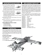
REPLACEMENT PARTS LIST

Replacement parts for the Great Planes Factor 30cc ARF are 
available using the order numbers in the Replacement Parts 
List that follows. The fastest, most economical service can 
be provided by your hobby dealer or mail-order company. 
Not all parts are available separately (an aileron cannot be 
purchased separately, but is only available with the wing kit). 
Replacement parts are not available from Product Support, 
but can be purchased from hobby shops or mail order/Internet 
order fi rms. Hardware items (screws, nuts, bolts) are also 
available from these outlets. 

To locate a hobby dealer, visit www.greatplanes.com and 

click on “Where to Buy”. Follow the instructions provided on 
the page to locate a U.S., Canadian or International dealer. 

GPMA2475 Fuselage
GPMA2476 Wing
GPMA2477 

Tail Surface Set

GPMA2478 Canopy/Hatch
GPMA2479 Wing 

Tube

GPMA2480 Landing 

Gear

GPMA2481 Wheel 

Pants

GPMA2482 Cowl
GPMA2483 Decal
GPMA2484 

EP Motor Mount Box

GPMA2485 Battery 

Tray

GPMA2486 Spinner
GPMA5390 

Tail Wheel Assembly

GPMA5391 

Hatch/Battery Tray Screws

Summary of Contents for Factor 30cc

Page 1: ...e In that Great Planes has no control over the final assembly or material used for final assembly no liability shall be assumed nor accepted for any damage resulting from the use by the user of the fi...

Page 2: ...f not assembled and operated correctly could possibly cause injury to yourself or spectators and damage to property 2 You must assemble the model according to the instructions Do not alter or modify t...

Page 3: ...8 2 0 ci two stroke gasoline engine The Factor 30cc ARF is designed to use the DLE 30 DLE 35RA or O S GT33 Other engines can also be used but you may need to make modifications for mounting those engi...

Page 4: ...Propeller Drill Guide DLEQ0301 Covering Tools Top Flite MonoKote Sealing Iron TOPR2100 Top Flite Hot Sock Iron Cover TOPR2175 Top Flite MonoKote Trim Seal Iron TOPR2200 Top Flite MonoKote Heat Gun TO...

Page 5: ...porting defective or missing parts use the part names exactly as they are written in the instruction manual Great Planes Product Support 3002 N Apollo Drive Suite 1 Champaign IL 61822 Ph 217 398 8970...

Page 6: ...with a covering iron ASSEMBLE THE WING Aileron Servo Installation BEGIN WITH THE LEFT WING PANEL 1 Install a servo lead extension not included and secure the connection 2 Install grommets and eyelets...

Page 7: ...Install servo horn 7 Aileron pushrod components 8 Install the 4 40 threaded clevis 9 Attach clevis to control horn 10 Position control horn on aileron 11 Mount control horn 12 Install the solder clev...

Page 8: ...llow the part to cool naturally Make sure the joint is thoroughly soldered It should be shiny not rough Reheat if necessary Wipe off the flux residue with denatured alcohol Coat the joint with oil to...

Page 9: ...to glue the stabilizer in the fuselage Wipe off any excess epoxy with a paper towel and denatured alcohol 7 Clean the tail gear wire 8 Position the tail gear by temporarily installing the rudder 9 Ce...

Page 10: ...Use 30 minute epoxy to glue in the hinges 12 Install the set screws in the wheel collars 13 Install the tail wheel 14 Install the two elevators following the same procedure used for installing the ru...

Page 11: ...he Main Landing Gear 1 Install the 3 16 5mm axles 2 Cut the axle to length 3 File a flat spot at the end of the axle 4 Install the wheels 5 Install the wheel pants 6 Install the main landing gear on t...

Page 12: ...nd plug it into the receiver Switch on the transmitter and temporarily plug the receiver battery into the receiver 4 Install and center the rudder servo arm 5 Cut the 110 2800mm pull pull cable in hal...

Page 13: ...ch rudder control horns 11 Attach a second set of clevises 4 40 couplers 4 40 nuts and silicone clevis retainers to the rudder control horns 12 Attach the clevises to the control horns and pull the ca...

Page 14: ...or servos The two servo leads can be joined with a Y harness and plugged into the receiver or each servo can be plugged into a separate channel in the receiver 15 Install the elevator control horns an...

Page 15: ...tion page 7 if a gas engine will be installed 1 Use epoxy to glue the front and back plates of the motor box together and secure the 6 32 blind nuts with thin CA 2 Glue the sides on using epoxy 3 Glue...

Page 16: ...all 8 Install the RimFire 1 60 motor 9 Install the forward battery hatch in the fuselage 10 Mount the ESC Connect the wires from the ESC to the motor wires Plug the ESC into the receiver Assemble the...

Page 17: ...e the epoxy cures insert the battery tray in the fuselage and check that the holes line up 4 Securely glue the 4 x 7mm blind nut in the plate 5 Make two battery straps from the supplied hook and loop...

Page 18: ...ncluded to the battery tray and the opposite side to the battery 9 Secure the flight batteries on the battery tray 10 Secure the battery tray in the fuselage 11 Install the receiver battery tray 12 Ma...

Page 19: ...bit drill the firewall for your engine The DLE30 and O S GT33 are rotated 17 degrees so that the muffler remains inside the cowl 2 Install the pivot ball on the throttle and choke arm 3 Temporarily mo...

Page 20: ...pper in the fuel tank Mark the top of the tank 2 Solder fuel line barbs onto one end of the brass tubes 3 Insert the brass tubes in the fuel tank stopper and stopper plates Loosely install the fuel ta...

Page 21: ...ree straps from the hook and loop material 11 Wrap the ignition module in foam and secure it to the bottom of the fuselage with a hook and loop strap 12 Install the ignition switch An ignition battery...

Page 22: ...ublers to the bottom of the throttle servo tray 2 Install the throttle servo tray 3 Make two straps from the remaining hook and loop material Install the receiver battery and receiver switch 4 Install...

Page 23: ...shrod from the throttle to install the threaded rod 10 Cut the outer pushrod tube 11 Roughen the outer pushrod tube with sandpaper 12 Install the outer pushrod tube 13 Slide a plywood outer pushrod su...

Page 24: ...letely stopping the engine 15 Glue the outer pushrod support to the outer pushrod and the fuselage 16 The optional choke pushrod is installed following the same procedure except the end of the pushrod...

Page 25: ...pushrod 2 Install the pivot ball socket Install the Cowl For the electric installation skip to step 2 1 Trim the cowl as shown to clear the muffler exhaust pipes and provide enough cooling air exit 2...

Page 26: ...per towel to wipe most of the water away 4 Use a piece of soft balsa or something similar to squeegee the remaining water from under the decal Apply the rest of the decals using the same method GET TH...

Page 27: ...ight Left 2 3 8 60mm 16 RUDDER AILERONS LOW RATE HIGH RATE Up Down 4 1 4 108mm 37 Up Down 1 7 8 47mm 23 Right Left 4 1 2 114mm 31 3D RATE If your radio does not have the ability to set three throw rat...

Page 28: ...220mm 1 Mark the C G location 2 With the plane ready to fly with an empty fuel tank or motor batteries installed use a Great Planes C G Machine or apply narrow 1 16 2mm strips of tape at the front an...

Page 29: ...tick or electric starter to start the engine If you do flip the propeller with your fingers wear a heavy leather glove such as a welder s glove When hand starting gas engines if the engine should back...

Page 30: ...ns Commission 5 I will not knowingly operate my model within three miles of any pre existing flying site except in accordance with the frequency sharing agreement listed in the complete AMA Safety Cod...

Page 31: ...e Mind your fuel level but use this first flight to become familiar with your model before landing Landing The Factor 30cc is easy to land We recommend landing on high rate throws To initiate a landin...

Page 32: ...6 RUDDER AILERONS C G 3D RATE Up and Down 4 1 4 108mm 37 Up and Down 1 7 8 47mm 23 Right Left 4 1 2 114mm 31 Forward 7 1 2 190mm from leading edge Aft 8 1 8 220mm from leading edge Receiver Battery Ig...

Reviews: