


26
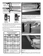
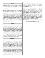
Pushrod Farther Out
Pushrod Farther Out
LESS
THROW
Pushrod Closer In
MORE
THROW
MORE
THROW
Pushrod Closer In
LESS
THROW
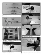
❏
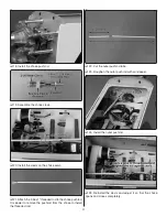
2. Adjust the location of the pushrod on the servo arm or
on the control horn fi rst. Then, use the endpoint adjustment
in your transmitter to fi ne tune the throws.
❏
3. Measure and set the
low
rate
throws. Measure and
set the high and low rate throws for the rest of the control
surfaces the same way.
If your radio does not have dual rates, we recommend setting
the throws at the high rate settings.
These are the recommended
control surface throws:
ELEV
A
T
OR
HIGH RATE
LOW RATE
7/8"
[22mm]
13°
Up
7/8"
[22mm]
13°
Down
5/8"
[16mm]
9°
Up
5/8"
[16mm]
9°
Down
3/4"
[19mm]
17°
Up
3/4"
[19mm]
17°
Down
1/2"
[13mm]
12°
Up
1/2"
[13mm]
12°
Down
7/8"
[22mm]
20°
Down
2"
[51mm]
19°
Right
2"
[51mm]
19°
Left
1-3/4"
[44mm]
17°
Right
1-3/4"
[44mm]
17°
Left
R
UDDER
AILER
ONS
FLAPS
Mix in approximately 5/16" [8mm]
down elevator with the flap.
This will reduce ballooning when
flaps are applied.
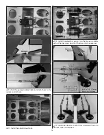
❏
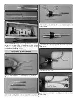
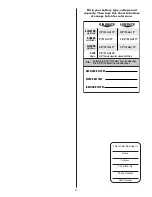
4. Once the throws are set, apply a drop of threadlocker
to the threads and tighten the 4-40 nuts against the clevises.
Slide the silicone retainers over the clevises.
IMPORTANT:
Now that you have the throws set, be sure
to set the failsafe on the radio.
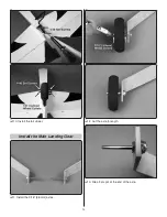
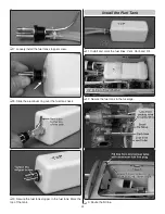
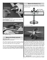
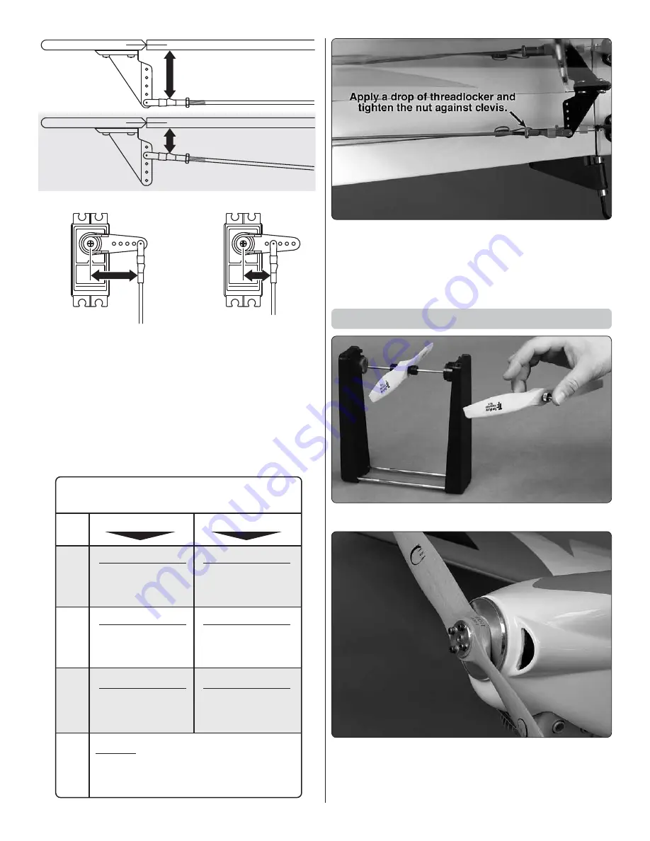
Install the Propeller
❏
1. Balance the propeller.
❏
2. Install the propeller. Drill holes through the propeller if
necessary.
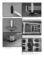
NOTE:
Enlarge the hole in the spinner backplate to 25/64”
[10mm] for the adapter ring used on the O.S. GT33 engine.
Summary of Contents for ESCAPADE MX 30cc
Page 32: ......