GREAT PLAINS Nutri-Pro NP30L Operator'S Manual Download Page 88

2018-10-10

Table of Contents

Index

407-313M

NP30L or NP40L

Table of Contents

Index

Adjustments

84

Nutri-Pro

®

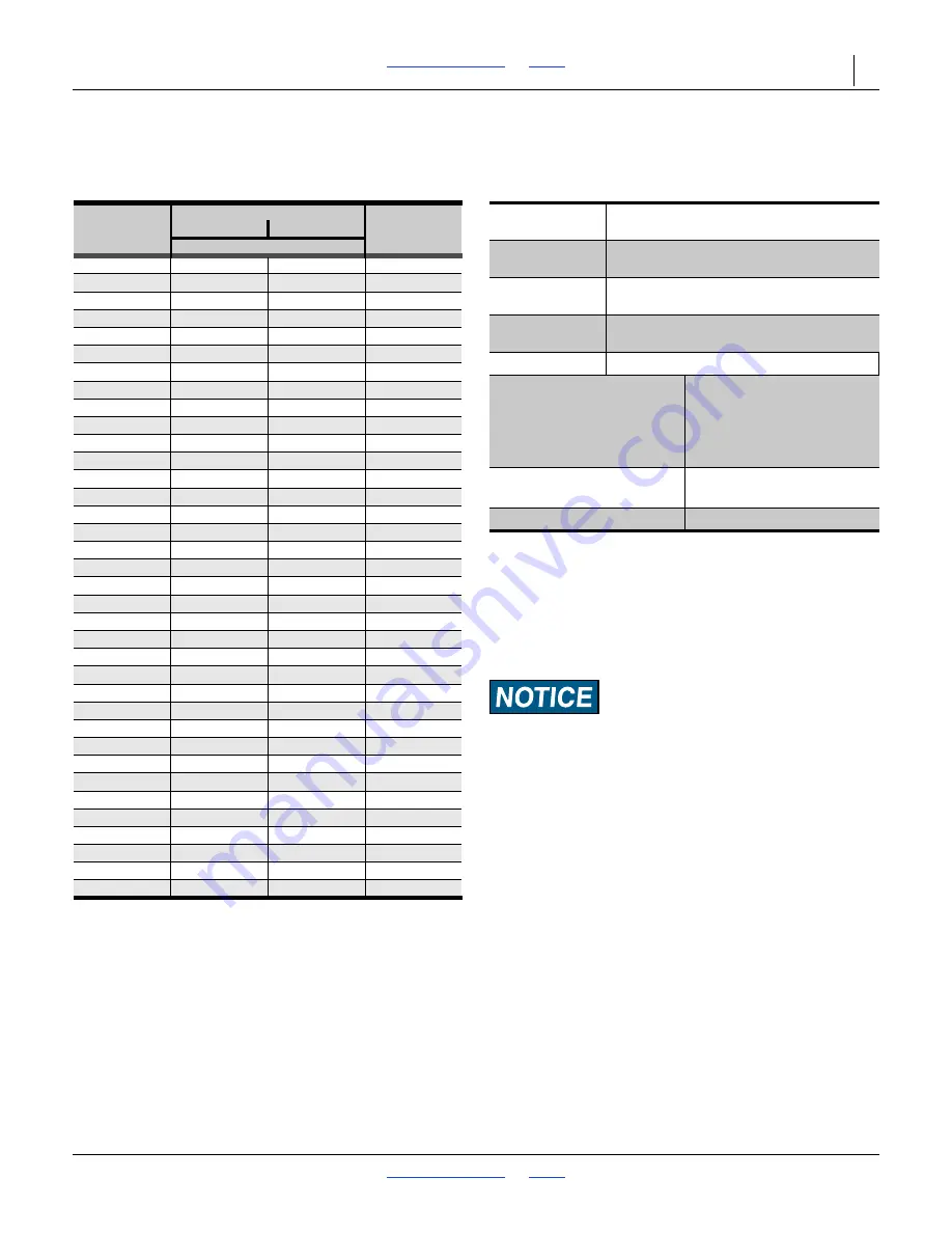
 NP40L-15R30 Fertilizer Rate

Use the slide chart or internet calculator for more precise 
rate setting.

NP40L-15R30 JohnBlue Reference Data

Use the data below with the CDS-John Blue 115797-01 
slide chart or with the CDS-John Blue internet calculator.

Equipment Damage Risk:

Plant at or below 9 mph (14.4 kph) with the 47T Driving
sprocket installed. The pump is rated for 450 rpm maximum,
which is exceeded at and above 9 mph (14.4 kph).

Drivin

g


S

procket

15

47

Dial 

S

ettin

g

4

2.5

3

7

5

3

.1

47

6

3

.7

56

7

4.4

65

8

5.0

75

9

5.6

8

4

10

6.2

2.0

94

11

6.9

2.2

10

3

12

7.5

2.4

112

1

3

8

.1

2.6

122

14

8

.7

2.

8

1

3

1

15

9.4

3

.0

140

16

10.0

3

.2

150

17

3

.4

159

1

8

3

.6

16

8

19

3

.

8

17

8

20

4.0

1

8

7

21

4.2

196

22

4.4

206

2

3

4.6

215

24

4.

8

224

25

5.0

2

3

4

26

5.2

24

3

27

5.4

25

3

2

8

5.6

262

29

5.

8

271

3

0

6.0

2

8

1

3

1

6.2

290

3

2

6.4

299

33

6.6

3

09

3

4

6.

8

3

1

8

3

5

7.0

3

27

3

6

7.2

33

7

3

7

7.4

3

46

38

7.6

3

55

3

9

7.

8

3

65

3

1657d

Gallon

s

per

Acre

Liter

s

per

Hectare

Pump Type

(•) Piston Pump

NGP-7050 Series

Data

Preference

(•) <user-specified>

Application 

Rate

<user-specified>

Drive

System

(•) Ground Drive

Loaded Radius: 17.55 in. (44.58 cm)

Swath Width

450 inches (1143 cm)

Drive

(Required):

(Optional):
(Optional):
(Optional):

25

15 or 47

__
__

Driven

(Required):

(Optional):
(Optional):
(Optional):

15
15
__
__

Sprocket Ratio

(for slide chart)

Driving 15T:
Driving 47T:

1.67

a

5.22

b

a. For easier scale readings (but same net ratio), use:

Loaded Radius: 20
Sprocket Ratio: 1.9

b. For easier scale readings (but same net ratio), use:

Loaded Radius: 10
Sprocket Ratio: 3.0

Ground Speed

5 mph

c

 / 8 kph

c. Gallons per acre is independent of speed between 2 mph 

and 9 mph (3-14 kph). See advisory below.

Summary of Contents for Nutri-Pro NP30L

Page 1: ...P40L 30 and 40 Foot Liquid Fertilizer Applicators Read the Operator manual entirely When you see this symbol the subsequent instructions and warnings are serious follow without exception Your life and the lives of others depend on it Illustrations may show optional equipment not supplied with standard unit or may show NP30A NP40A NP3000 or NP4000 models where the topic function is identical 38809 ...

Page 2: ...Table of Contents Index Table of Contents Index ...

Page 3: ...Hitching 26 Full 3 Point Hitching 27 Pull Type Hitching 27 Electrical Hookup 28 Hydraulic Hose Hookup 29 Hydraulic Pump Hookup Option 30 Raise Parking Stands newer applicators 31 Raise Parking Stands older applicators 31 Leveling Implement 32 Set Application Depth 32 3 Point Leveling 32 2 Point Front to Back Level Spacers 32 Pull Type Hitch Leveling 33 Meter Setup Option 34 Operating Instructions ...

Page 4: ...i Pro NP30L 12R30 Fertilizer Rate 82 NP30L 12R30 JohnBlue Reference Data 82 Nutri Pro NP30L 13R30 Fertilizer Rate 83 NP30L 13R30 JohnBlue Reference Data 83 Nutri Pro NP40L 15R30 Fertilizer Rate 84 NP40L 15R30 JohnBlue Reference Data 84 Nutri Pro NP40L 16R30 Fertilizer Rate 85 NP40L 16R30 JohnBlue Reference Data 85 Nutri Pro NP40L 17R30 Fertilizer Rate 86 NP40L 17R30 JohnBlue Reference Data 86 Nutr...

Page 5: ...ord is limited to the most extreme situations typically for machine components that for functional purposes cannot be guarded WARNING indicates a potentially hazardous situation which if not avoided could result in death or serious injury and includes hazards that are exposed when guards are removed It may also be used to alert against unsafe practices CAUTION indicates a potentially hazardous sit...

Page 6: ...plying dusts wettable powders or granules or if being exposed to spray mist Cartridge type respirator approved for pesticide vapors unless label specifies another type of respirator Waterproof unlined gloves Neoprene is recommended Cloth coveralls outer clothing changed daily waterproof items if there is a chance of becoming wet with spray Waterproof boots or foot coverings Do not wear contaminate...

Page 7: ...and RVS III Radars are intentional radiators of RF energy Although its radiated energy level is far below the limits set by EN 61010 1 1993 A2 1995 Chapter 12 4 it is advisable not to look directly into the face of the unit The radar must radiate toward the ground and at least 20 cm 8 inches away from a human during use to comply with the RF human exposure limits as called out in FCC 47 CFR Sec 2 ...

Page 8: ... need to be in line contact for the hazard to exist Maintain at least 10 foot 3 m clearance Electrocution can occur without direct contact between the energized fertilizer applicator and a person near the fertilizer applicator Watch for sagging damaged or low electrical lines The folded fertilizer applicator could contact lines lower than 13 ft 4 m Overhead lines at farm structures are a particula...

Page 9: ...ght of towing vehicle Do not transport a 3 point implement that exceeds the capacity or ballasting of the tractor There may not be enough front wheel traction for safe steering Carry reflectors or flags to mark fertilizer applicator in case of breakdown on the road Keep clear of overhead power lines and other obstructions when transporting Refer to transport dimensions under Specifications and Cap...

Page 10: ...ould affect their health consult a doctor immediately with the chemical label or container in hand Any delay could cause serious illness or death Dispose of empty chemical containers properly By law rinsing of the used chemical container must be repeated three times Puncture the container to prevent future use An alternative is to jet rinse or pressure rinse the container Wash hands and face befor...

Page 11: ...lement to reach ambient temperature before commencing maintenance Disconnect battery ground cable before servicing or adjusting electrical systems or before welding on fertilizer applicator Inspect all parts Make sure parts are in good condition and installed properly Remove buildup of grease oil or debris Remove all tools and unused parts from implement before operation Safety At All Times Thorou...

Page 12: ...Replace all damaged or missing decals Order new decals from your Great Plains dealer Refer to this section for proper decal placement When ordering new parts or components also request corresponding safety decals To install new decals 1 Clean the area on which the decal is to be placed 2 Peel backing from decal Press firmly on surface being careful not to cause air bubbles under decal 818 055C Slo...

Page 13: ...ype shown On outside face of lift assist brackets 2 Point On the outside faces of casters 3 Point Models on the outside faces of lift assist brace weldments 4 or 6 total 38815 838 267C Daytime Reflectors On each light bracket back face outside ends of the top transport rest tube 4 total 38815 818 323C Danger Possible Chemical Hazard Option on the mount of each ground drive 0 1 or 2 total 31589 ...

Page 14: ...s in Spanish warning users to seek translation assistance if they do not speak English Pull Type On top of left tongue tube near hitch 2 Point 3 Point On front face of frame tube left of hitch 1 total 38815 818 590C Danger Hitch Crush On front of frame tube 2 total 38815 838 599C Danger Electrocution On frame tube near wing hinges 2 total 38815 ...

Page 15: ...nt tool bar right of center 1 total 38815 818 339C Warning High Pressure Fluid Hazard Pull Type On top of left tongue tube near hitch 1 total 38815 818 437C Warning High Pressure Fluid Hazard On front face of front tool bar left of center Pull Type On mount of each front caster wheel Pull Type and 2 point On each lift assist mount 1 3 or 7 total 38818 38815 ...

Page 16: ...ing Moving Parts Option On mount of each ground drive 0 1 or 2 total 31085 848 551C Warning Towing On decal mount near rear hitch 1 total See Transport on page 56 and Hitching Nurse Tank on page 58 for further information 38815 818 398C Caution Tires Not a Step 2 and 3 Point outside faces of manual gauge wheel arms 2 total 31050 ...

Page 17: ...nt face of front tool bar right of center 1 total 38815 818 719C Caution Read Operator s Manual On front face of front tool bar left of center 1 total 38815 838 092C Caution Tire Pressure and Bolt Torque NP30L all NP40L 15 Row and 31 Row Pull type on valve stem side of each front caster wheel rim Pull type 2 point each lift assist tire rim 0 2 or 6 total 31052 ...

Page 18: ...595C Torque wheel bolts to 120 lb ft Maximum inflation pressure of tires is 90 psi To Avoid Injury or Machine Damage from Improper Tire Inflation or Torquing of Wheel Bolts CAUTION 31050 848 846C Caution Tire Pressure and Bolt Torque NP40L 16 Row and 17 Row Pull type on valve stem side of each front caster wheel rim Pull type 2 point each lift assist tire rim 0 2 or 6 total 848 846C Maximum inflat...

Page 19: ...the 3 section variable rate manifold Intended Usage Use the NP30L or NP40L Fertilizer Applicator to apply compatible liquid fertilizers Do not modify Great Plains provisioned components or install user provisioned components except as authorized or recommended by Great Plains Document Family Conventional Liquid Fertilizer Models NP30L 11R30 30 Foot 11 Row 30 inch NP30L 12R30 30 Foot 12 Row 30 inch...

Page 20: ...ld only be replaced with Great Plains specified parts Always use the serial and model number when ordering parts from your Great Plains dealer Refer to Figure 2 For 2013 5 section applicators the serial number plate is located on the center section on the front face of the left front fold cylinder mount Refer to Figure 3 For 2012 5 section applicators the serial number plate is located on the cent...

Page 21: ...r are otherwise dissatisfied please take the following actions first 1 Discuss the matter with your dealership service manager Make sure they are aware of any problems so they can assist you 2 If you are still unsatisfied seek out the owner or general manager of the dealership If your dealer is unable to resolve the problem or the issue is parts related please contact Great Plains Service Departme...

Page 22: ...ts Index 18 Metering Overview Hydraulic Drive System Components Options See page 21 to page 24 for callout descriptions L12 L11 L13 L14 L15 L16 L17 L24 L25 L30 L38 L40 L41 L43 L45 L39 L46 L47 L48 L49 L50 L51 L52 L54 L53 L55 L56 Figure 5 Options Hydraulic Drive Plumbing 36031 ...

Page 23: ...ble of Contents Index 407 313M Ground Drive Preset Rate System See page 21 to page 24 for callout descriptions Figure 6 Ground Drive Preset Rate Plumbing 31646 L11 L14 L12 L13 L16 L17 L24 L25 L15 L30 L31 L32 L33 L34 L35 L36 L37 L42 L46 L47 L48 L49 L50 L51 L52 L53 L54 L55 L56 ...

Page 24: ...g and setup requirements differ for preset rate ground drive variable rate ground drive and variable rate hydraulic drive applicators The next few pages provide an overview of both systems Figure 7 Variable Rate Ground Drive Plumbing 31647 L12 L13 L14 L11 L15 L18 L21 L16 L19 L22 L17 L20 L23 L24 L25 L29 L28 L27 L27 L30 L33 L32 L32 L37 L36 L35 L34 L41 L40 L43 L44 L45 L49 L50 L51 L52 L53 L54 L55 L56 ...

Page 25: ...pplication rates intended A hose ID of 11 2 inch or larger suffices L16 Tank Supply Hose Shut off Valve This Nutri Pro manual mentions only a single shutoff valve for the tank supply hose Your tank may have additional shutoff and or flow management valves Consult your tank manual L17 Tank Supply Hose Quick Coupler The supply inlet for ground drive NP30L or NP40L applicators is a 2 inch male cam lo...

Page 26: ...se fitting must be or be adapted to 2 inch FCL L27 Return Outlet Shut Off Valve variable rate ground drive implements only This valve is open for application and clean out and closed at all other times L28 Bypass Return Outlet variable rate ground drive implements only The return outlet of the NP30L or NP40L applicator is a 3 4 inch cam lock quick coupler plug male MCL The tank bypass return hose ...

Page 27: ... variable rate manifold As it detects variations from your desired rate it signals the console to adjust the control valve L42 Passive Manifold used only with preset rate implements This plumbing cross splits the flow into three sections Equal flow is assured by the orifice plates L43 Section Valves variable rate only There are three On Off solenoid valves 1 2 3 These open and close under the cont...

Page 28: ...scosity of the material being applied See page 88 for plate selection and installation L52 Nozzle Body This fitting adapts the boom clamp to tubing and may be positioned for forward or rear tubing direction L53 VeriFlow Nozzle Option This accessory replaces components and with a spring regulated valve nozzle that requires no adjustment or orifice plate changes over a wide range of flow rates L54 D...

Page 29: ...rtial fold on 2 Point page 140 Install optional variable rate console in tractor page 142 Install other Options not factory or dealer installed Post Delivery Seasonal Setup On initial delivery use with a new tractor and seasonally check and as necessary complete these items before continuing to the routine setup items Bleed hydraulic system page 105 De grease exposed cylinder rods if so protected ...

Page 30: ...r Category III tractors Refer to Figure 8 This implement is factory set for Category III tractors Category II requires an optional hitch pin kit see page 115 In addition the following bushings not supplied by Great Plains may be needed to fit your quick hitch or tractor s 3 point arms Upper Link full 3 point only 1 inch 25 4 mm I D x 11 4 inch 31 8 mm O D Lower Links 11 8 inch 28 6 mm I D x 17 16 ...

Page 31: ...p tractor engine and set parking brake before attaching cables and hoses Refer to Figure 10 1 Use jack to raise and lower applicator tongue 2 Back tractor draw bar into alignment with hitch 3 Secure with a locking hitch pin Loss of Control Hazard If a nurse tank will be used do not operate without a locking hitch pin A pin working loose could cause abrupt implement motions resulting in a tank upse...

Page 32: ...onsole flow harness connector optional Hydraulic connector 2013 2 point 5 section only Console pressure connector variable rate only Console speed connector optional and only if sensor radar mounted on implement ___________________________ Make sure tractor is shut down with accessory power off before making connections These connections may be made in any order The key requirement is that all con...

Page 33: ...tb implement connect either hose to either side of the remote Use a regular remote and not a dedicated tractor 3 point remotec Secure hoses and cables so that they have sufficient slack for hitch movements but cannot get caught between moving parts of fertilizer applicator Failure to safely route and secure hoses and cables could result in damage requiring component repair replacement and lost fie...

Page 34: ...in applicator functions 1 Connect the pump hydraulic hoses to suitable tractor remotes Refer to Figure 14 2 The pressure hose coming out of the tractor remotes must be connected to the motor inlet port I Base end on hose label and the return line connected to the motor outlet O Rod end on hose label 3 Before operating place a stop in the neutral position for the tractor hydraulics so that the hydr...

Page 35: ... pins Secure with cotters Raise Parking Stands older applicators This applies to 2 point lift assist hitching and 3 point hitching but not pull type hitching as the tongue parking stand was already stored at an earlier step Refer to Figure 16 1 Use tractor 3 point hitch and if so equipped the lift assist circuit to slightly raise the implement See Raising Lowering Applicator on page 44 2 Remove th...

Page 36: ...the ground in representative conditions 3 Point Leveling Refer to Figure 17 Leveling is controlled entirely by the tractor hitch 2 Point Front to Back Level Spacers The rear lift assist assembly must be set to match the gauge wheels and 2 point hitch in front Lift assist lowered height is controlled by provided spacers on the lift cylinder rods To set 1 Lower implement until lift assist wheels are...

Page 37: ...itch height of 16 75 inches 42 5 cm measured from the bottom of the tongue to the ground Refer to Figure 19 Sudden Hitch Slump or Failure Risks Always have two bolts through two holes on both hitch and tongue Never rely on a single bolt To obtain the correct height and a level tongue remove the two hitch bolts and reposition the fertilizer applicator hitch on the tongue The hitch can be inverted i...

Page 38: ...e Raven SCS 450 manual or the Calibration Card for the keystroke sequence for setting each of these values SCS 450 BOOM CAL The variable rate Nutri Pro has three boom sections BOOM 1 BOOM 2 and BOOM 3 The BOOM CAL number is the swath of each section Use the values from the following table These values presume one fertilizer drop line per row in row The booms have extra drops per section If using o...

Page 39: ...system diagrams in this manual Obtain this number from the tag affixed to the meter Enter it into the SCS 450 and record on the Calibration Card SCS 450 VALVE CAL This is the response time calibration number for the control valve in system diagrams in this manual Obtain this number from the tag affixed to the valve Enter it into the SCS 450 and record on the Calibration Card SCS 450 PRESSURE CAL T...

Page 40: ...nsumed as measured by the flow meter is continuously subtracted from this number and may be used to signal a low tank alarm The number needs to be re entered at each refill SCS 450 TIME Optional The SCS 450 which is always in 24 00 hour time format defaults to 00 00 and resets to that after 10 days of inactivity You may use this menu to set the actual time 31584 31584 ...

Page 41: ...r Lubrication and Scheduled Maintenance on page 109 Check all tires for proper inflation See Tire Inflation Chart on page 122 Check all bolts pins and fasteners Torque as shown in Torque Values Chart on page 122 Check fertilizer applicator for worn or damaged parts Repair or replace parts before going to the field Check hydraulic hoses fittings and cylinders for leaks Repair or replace before goin...

Page 42: ...all center section wheel lock channels 7 Lower fertilizer applicator onto lock channels 8 Set lift circuit to Float Pull Type 2 Point 3 Point NP30L Lift Assist Locks Front Caster Wheel Lock Channels Lift Assist Locks Wing Lock Channels Wing Lock Channels NP40L 2012 3 section frame Lift Assist Locks Front Caster Wheel Lock Channels Wing Transport Lock All 5 Section Lift Assist Locks Wing Lock Chann...

Page 43: ...In routine use install only the center section locks For maintenance install all four Installing the left wing lock requires disabling the hydraulic depth stop Falling Hazard Do not climb or stand on tires or wheels Even at full extension on level ground tires may not be in firm ground contact They could spin without warning A fall could result in serious injury Refer to Figure 23 and Figure 24 To...

Page 44: ...annels 8 Set lift circuit to Float Wing Lock Channels Refer to Figure 26 These lock channels are only present on 2012 NP40A NP30A NP3000 2 point with lift assist and 3 point models They enable a partial gull wing fold during field lift On 2013 5 section models this function is controlled by solenoid valves See page 51 for operation Wing Lock Pins These pins are present only on NP40A models with 5 ...

Page 45: ...ings into engagement on the pins of the outer wing stop post At the start of unfold the latches restrain the outer wings causing the inner wings to unfold first As the inner wings near the ground the latches fall away allowing the outer wings to unfold Solenoid Valves These valves are present only on 2013 2 Point NP40A models They normally require no operator attention See 2013 NP40A 2 Point Fold ...

Page 46: ...s might otherwise be able contact each other in unusual circumstances When unfolded the latch pivots out and down disengaged During fold the outer wing folds first until the stop posts contact each other As the inner wing then folds and passes vertical the latch swings into engagement on the pins of the outer wing stop post At the start of unfold the latches restrain the outer wings causing the in...

Page 47: ... illuminated lamp indicates power sent to the harness The harness must be connected at the hitch for the function to be effected Switch Positions PARK All solenoid valves are powered off and are spring loaded to flow open positions Use this position only for parking to save tractor battery power With the switch in PARK any hydraulic flow to the fold lift circuit may have undesired results FOLD UNF...

Page 48: ...rdless of applicator hitch type The lift circuits are re phasing master slave on pull type and 3 section or 2012 2 point See Re Phasing Pull Type Lift System on page 45 The applicator may be raised and lowered while folded Weight Transfer Shut Off Valve This applies to all 3 section all pull type all 3 point and all 2012 NP40A 3 and 5 section The 2013 5 section 2 point weight transfer has no inter...

Page 49: ...rs to the depth set at the hydraulic depth stop at the left front caster wheel See Hydraulic Depth Stop Adjustment on page 70 for details on height adjustment Gradual Crushing Hazard Do not rely on hydraulic pressure alone to keep the fertilizer applicator raised Use transport lift locks page 38 when working around a raised fertilizer applicator The bypass orifices in the re phasing system cause i...

Page 50: ...ngs level Set circuit to Neutral 2 Lift the center section with the 3 point Raising 3 Point Transport Service Lift Folded If the wings are already folded and are being left that way you may raise and lower the 3 point hitch without touching the fold circuit Lowering 3 Point Field Lower Unfolded See sidebar for first pass 1 Lower the 3 point hitch to field setting 2 Set hitch to Depth Control mode ...

Page 51: ...ircuit to Neutral 2 Raise the tractor hitch This raises the knives or tines with a slight forward motion preventing plugging of the ammonia tube outlets 3 Extend the lift assist cylinders normally with an Extend operation of the tractor remote Note Holding the lift assist circuit at raised for a few seconds re phases the cylinders 4 When fully raised set all remotes to Neutral Raising 2012 3 Secti...

Page 52: ...nt Service Parking Folded This topic presumes that the intention is to lower a folded applicator without unfolding If the intention is to both lower and unfold see Unfolding 3 Section 2012 5 Section 2 Point on page 52 1 Close the weight transfer shut off valve page 47 2 Raise the applicator Set circuits to Neutral 3 Remove spacers page 34 and install lift assist lock channels Deploy parking stands...

Page 53: ...s are installed on the lift assist cylinders page 39 that wing lock pins are not in the locking holes page 41 and that the hydraulic harness is connected at the hitch page 28 2 Raise the tractor 3 point hitch enough to lift gauge wheels coulters and the parking stand bases off the ground Set the hitch circuit to Neutral Refer to Figure 35 depicting an NP4000 with similar fold system 3 Set the FOLD...

Page 54: ...ator is 5 section remove the wing transport lock pins page 41 3 Extend the fold cylinders to unfold 4 Set control to Float when wing front caster wheels contact the ground 5 Extend the lift circuit page 45 to raise the implement fully 6 Remove and store the transport locks at center section and lift assist cylinders page 38 If wing lift cylinder lock channels were installed Remove them and re enga...

Page 55: ...the ground first Take precautions if parking surface damage is a concern 1 Fully raise the 3 Point hitch 2 Close the weight transfer shut off valve page 44 3 Point the applicator into the wind 4 Deploy parking stands Set them to maximum height 5 Extend fold cylinders 6 As the wings near level set circuit to Neutral 7 Unless using blocks or stands fully extend the gauge wheels to maximum height 8 R...

Page 56: ...er the applicator at the rear and lower the 2 point hitch in the front 8 Set the hitch to Depth Control mode Set both fold and lift assist circuits to Float 9 Open the weight transfer shut off valve Unfolding 3 Section 2012 5 Section 2 Point Service To unfold off field for servicing unfold with the center section fully raised Unless the wing gauge wheels have been previously extended to maximum he...

Page 57: ...r lines to discharge 6 Activate lift assist again in case the cylinders have settled during discharge 7 Cautiously approach the rear of the applicator Install lift locks at the rear casters 8 Deploy parking stands if the applicator is to be parked at the folding spot Refer to Figure 38 9 Swing the wing locks up and out of their engaged positions and into their reset positions 10 Retract the fold c...

Page 58: ... to raise the lift assist off the lock channels 5 Set all circuits to Neutral Shut off the tractor 6 Remove the lift assist lock channels page 39 Install the spacers page 34 7 If wing gauge wheels were extended crank them to field height page 68 8 Lower the hitch to field height Notes about normal unfold Inner wings unfold first The outer wings are constrained by the wing latches page 42 Outer win...

Page 59: ...d lines with or without direct contact It is also too high for safe transport Refer to Figure 42 3 Raise the hitch 4 Retract the fold lift circuit to simultaneously raise and fold the applicator Observe the fold sequence Lift and fold do not start and end at the same time If an abnormal fold is detected set the fold lift circuit to Retract then Neutral at wings level Troubleshoot the problem 5 Set...

Page 60: ...is adequate for the task Using an inadequate tow vehicle is extremely unsafe and can result in loss of control serious injury and death Tractor weight matters For field configuration after transport tractor must weigh at least 150 of the implement plus the loaded nurse tank This weight is substantially higher than the required transport weight Loss of Control Hazard 2P 3P Never transport a 2 point...

Page 61: ...or page 47 4 Install lift cylinder locks 2 point page 38 5 Fold applicator if unfolded page 50 6 Plan the route Avoid steep hills 7 Always have lights on for highway operation 8 Do not exceed 32 kph 20 mph Comply with all national regional and local laws when traveling on public roads 9 Remember that the fertilizer applicator may be wider than the tractor Allow safe clearance 10 Transport slowly o...

Page 62: ...lement 2 Route tank supply hose to implement inlet Allow ample slack for tight field turns and uneven ground Do not leave so much slack that the hose can reach the ground 3 Remove plug from implement inlet and any cap on tank supply hose 4 Inspect and clean connector fittings 5 Mate connectors of tank and implement supply hoses Fold cam levers forward to lock Leave valves closed 6 If the tank has ...

Page 63: ...l console 9 Mind the fertilizer tank levels while planting both to a confirm expected consumption rate and b avoid running the pump dry 10 If residual fertilizer is not recovered at end of planting apply it to the last field planted 11 Clean out fertilizer system per page 103 Ground Drive Pauses and Turns When the implement is stopped or lifted the pump stops The boom is still pressurized but this...

Page 64: ...With the optional hydraulic drive system pauses cause the speed sensor to report zero speed which causes the console to close the flow control valve Set the pump hydraulic remote to Float if stopping for and extended period When the applicator is stopped or lifted the pump stops The boom is still pressurized but this bleeds down to 8 psi very quickly seconds at which point the nozzle clamp check v...

Page 65: ...s raised while in motion To conserve material and prevent unintended application set the MASTER switch to OFF when raising When stopping operating the MASTER switch is not usually necessary if the console has an active speed sensor data source If suspending application for more than a minute also set the pump motor hydraulic circuit to Float No console actions are required to suspend application w...

Page 66: ...on leave transport locks in 44 Unfold Implement 50 Row Units Checklist Page Check row cleaner setup Option 93 Check tubing connections to applicators Check outlet behind arms Check coulter blade condition Check coulter depth 66 Mechanical Checklist post Hitching Page Remove wing lock pins 41 Raise implement 44 Unfold wings 54 Remove lift assist locks 38 Install spacers 34 Check front to rear level...

Page 67: ... Suspending Application Checklist Page 1 Option Set hydraulic pump circuit to Float 2 Set console MASTER switch OFF 61 3 Stop tractor with applicator raised or left lowered Pass Turn Operation Checklist Page 1 Set console MASTER switch OFF some distance before end of pass or stop at end of pass 61 2 While slowing at end of pass or stopped 3a a These steps are for a full stop prior to a turn If the...

Page 68: ...jack to neutralize tongue weight at tractor hitch 7 Set hydraulic circuits to Float 8 Shut off tractor 9 Disconnect hydraulic lines Secure them so that they do not touch the ground 10 Disconnect electrical cables capping where provisioned 11 Disconnect any safety chain Unhitch Restart tractor and pull away from fertilizer applicator Long Term Storage 1 Conclude application per Ending Application o...

Page 69: ...epth consistency Application Depth and Coulter Adjustments 66 Trench depth and application height Weight Transfer 71 Application depth consistency Fertilizer Rate 34 Application rate Select and Install Orifice Plates 88 Consistent application rate across rows Strainer Adjustment 90 Minimize cavitation and orifice clogging Fertilizer Relief Valve Option 91 System protection minimizing material wast...

Page 70: ...ilable you can increase the spring down force to compensate In light but rocky conditions the factory spring setting may be higher than needed You can extend blade life by reducing the force at which the blades ride up over obstructions Applicator weight in almost all applicator configurations is generally sufficient to load the coulters to the full 400 pound factory setting Setting all springs ab...

Page 71: ... caster at the pivot casting Loosen the jam nuts at Loosen the set screws just enough to allow the casting to swivel Re tighten the jam nuts Do not remove the center stop screw 3 As blades wear keep the release height constant by raising the applicator weldment on the coulter arm Loosen the bolts Slide the weldment up Tighten the bolts If the application height is still too low after this adjustme...

Page 72: ...ound level 9 Check frame front to back level and adjust spacers page 34 as necessary 10 Adjust the gauge wheel heights to bring the wing coulters to the same height as the center section just above the ground 11 Measure the length of exposed gauge wheel arm tube 12 Crank the wheel up by the desired coulter depth exposed arm tube length becomes length plus the coulter depth Capture this setting by ...

Page 73: ...at ground level Check front to rear level 9 Adjust the gauge wheel heights to bring the wing coulters to the same height as the center section just above the ground 10 Measure the length of exposed gauge wheel arm tube 11 Crank the wheel up by the desired coulter depth exposed arm tube length becomes length plus the coulter depth Capture this setting by re inserting and securing the pin 12 At the ...

Page 74: ...t 3m and stop 7 Measure the depth at which the coulters are running If the coulters are at the desired depth no further adjustment is necessary Skip to step 12 8 Raise the implement and set the lift circuit to neutral 9 Adjust the stop up to increase depth or down to reduce depth Adjust in small increments 10 Check the new setting starting at step 5 11 Adjust weight transfer page 71 to hold wings ...

Page 75: ...f paper or cardboard NOT BODY PARTS to check for suspected leaks Wear protective gloves and safety glasses or goggles when working with hydraulic systems If an accident occurs seek immediate medical attention from a physician familiar with this type of injury Crushing Hazard Keep body parts clear of wings row cleaners and coulters while adjusting Keep all bystanders well away You will be seriously...

Page 76: ...or weight transfer When closed it bypasses the reducing valve for faster fold cylinder operation and faster 2 point lift assist The pressure reducing valve controls the flow to the cylinders The bypass valve returns excess oil to the tractor Adjust the weight transfer to achieve consistent coulter depth while keeping the wings level with the center section If insufficient weight is transferred out...

Page 77: ...g for step 7 through step 10 Note On 2 point implements fold and unfold are followed by lift and lower operations 7 Set tractor remote circuit for unfold Lock lever for continuous operation 8 At the pressure reducing valve release the lock disc 9 Adjust the knob for an initial value of 800 psi on the gauge Tighten the lock disc 10 At the bypass valve release the lock disc Adjust the bypass valve k...

Page 78: ...s It is incompatible with open center systems Note Do not set or adjust the weight transfer system if the outer wings are not level with the inner wings at unfold Do not use the weight transfer system to compensate for unfold stop adjustment issues See Unfold Stop Adjustment on page 77 Adjust the weight transfer to achieve consistent coulter depth while keeping the wings level with the center sect...

Page 79: ...all within the 1000 1500 PSI range 8 Release the lock disc 9 Adjust the knob for an initial value of 800 psi on the gauge Tighten the lock disc 10 Check that the bypass gauge is still in the green zone Adjust the tractor remote flow to correct Re check the reading on the pressure reducing gauge 11 Observe applicator operation and re adjust down pressure as necessary after oil warm up Repeat step 7...

Page 80: ...eyebolt to the top face of the front caster wheel lug tube To adjust the eyebolt loosen the hose guide nut and jam nut Rotate the adjust nut to set bolt reveal Tighten jam nut Rear Eyebolt Adjustment On 2 point and pull type implements side to side level at rear is controlled by eyebolts at the lift cylinder bases On 2 point rear height is set by spacers page 34 On pull type rear height is control...

Page 81: ...ace Raise and fold page 49 Install lift assist lock channels page 38 and parking stands page 31 3 Set the FOLD FIELD switch to FOLD Extend the fold lift circuit to unfold until the inner wings stop Set the circuit to Neutral Shut off the tractor 4 Check the sensor actuator gap at the affected wing pivot With the actuator near the marked region on the sensor the gap must be 1 8 to 1 4 inch 3 2 to 6...

Page 82: ...nels page 49 and parking stands page 31 3 Set the FOLD FIELD switch to FOLD Extend the fold lift circuit to unfold until the inner wings stop 4 Set the FOLD FIELD switch to FIELD Retract the fold lift circuit until the wings stop at gull wing field lift page 49 Set the circuit to Neutral Shut off the tractor 5 Check the sensor actuator gap at the affected wing pivot With the actuator near the mark...

Page 83: ...etting for a new piston is 1 Loosen the jam nut 2 Turn the bolt counterclockwise until the bolt is turning freely 3 Drive screw in down until it contacts spring plate 4 Drive screw in until the bolt reveal from top of welded nut to bottom of bolt head is 2 0 inches 5 1 cm 5 Tighten the jam nut Use more or less tension as needed to eliminate caster vibration during highway transport Adjust as neede...

Page 84: ...drive Range page 91 5 Set the ground drive dial page 92 6 Set the console rate see 016 0159 831 Raven SCS 450 Installation Operation and Service manual 7 Check the manifold pressure and relief valve during operation page 91 Determining Application Rate Great Plains recommends checking with your local agronomist as soil conditions vary Soil conditions in your area may need less or more fertilizer t...

Page 85: ...20 9 2 2 9 187 21 9 6 3 1 196 22 3 2 206 23 3 4 215 24 3 5 224 25 3 7 234 26 3 8 243 27 3 9 253 28 4 1 262 29 4 2 271 30 4 4 281 31 4 5 290 32 4 7 299 33 4 8 309 34 5 0 318 35 5 1 327 36 5 3 337 37 5 4 346 38 5 6 355 39 5 7 365 40 5 8 374 31657a Gallons per Acre Liters per Hectare Pump Type Piston Pump NGP 7050 Series Data Preference user specified Application Rate user specified Drive System Grou...

Page 86: ... 19 9 5 3 0 178 20 10 0 3 2 187 21 3 3 196 22 3 5 206 23 3 7 215 24 3 8 224 25 4 0 234 26 4 1 243 27 4 3 253 28 4 5 262 29 4 6 271 30 4 8 281 31 4 9 290 32 5 1 299 33 5 3 309 34 5 4 318 35 5 6 327 36 5 7 337 37 5 9 346 38 6 1 355 39 6 2 365 31657b Gallons per Acre Liters per Hectare Pump Type Piston Pump NGP 7050 Series Data Preference user specified Application Rate user specified Drive System Gr...

Page 87: ... 168 19 3 3 178 20 3 5 187 21 3 6 196 22 3 8 206 23 4 0 215 24 4 1 224 25 4 3 234 26 4 5 243 27 4 7 253 28 4 8 262 29 5 0 271 30 5 2 281 31 5 4 290 32 5 5 299 33 5 7 309 34 5 9 318 35 6 0 327 36 6 2 337 37 6 4 346 38 6 6 355 39 6 7 365 31657c Gallons per Acre Liters per Hectare Pump Type Piston Pump NGP 7050 Series Data Preference user specified Application Rate user specified Drive System Ground ...

Page 88: ...6 168 19 3 8 178 20 4 0 187 21 4 2 196 22 4 4 206 23 4 6 215 24 4 8 224 25 5 0 234 26 5 2 243 27 5 4 253 28 5 6 262 29 5 8 271 30 6 0 281 31 6 2 290 32 6 4 299 33 6 6 309 34 6 8 318 35 7 0 327 36 7 2 337 37 7 4 346 38 7 6 355 39 7 8 365 31657d Gallons per Acre Liters per Hectare Pump Type Piston Pump NGP 7050 Series Data Preference user specified Application Rate user specified Drive System Ground...

Page 89: ... 7 206 23 4 9 215 24 5 1 224 25 5 3 234 26 5 5 243 27 5 7 253 28 6 0 262 29 6 2 271 30 6 4 281 31 6 6 290 32 6 8 299 33 7 0 309 34 7 2 318 35 7 4 327 36 7 7 337 37 7 9 346 38 8 1 355 39 8 3 365 40 8 5 374 41 8 7 384 42 8 9 393 43 9 1 402 44 9 4 412 45 9 6 421 46 9 8 430 47 10 0 440 31657e Gallons per Acre Liters per Hectare Pump Type Piston Pump NGP 7050 Series Data Preference user specified Appli...

Page 90: ...7 21 4 7 196 22 5 0 206 23 5 2 215 24 5 4 224 25 5 6 234 26 5 9 243 27 6 1 253 28 6 3 262 29 6 6 271 30 6 8 281 31 7 0 290 32 7 2 299 33 7 5 309 34 7 7 318 35 7 9 327 36 8 1 337 37 8 4 346 38 8 6 355 39 8 8 365 40 9 0 374 41 9 3 384 42 9 5 393 43 9 7 402 44 9 9 412 31657f Gallons per Acre Liters per Hectare Pump Type Piston Pump NGP 7050 Series Data Preference user specified Application Rate user ...

Page 91: ...4 7 215 24 4 9 224 25 5 1 234 26 5 4 243 27 5 6 253 28 5 8 262 29 6 0 271 30 6 2 281 31 6 4 290 32 6 6 299 33 6 8 309 34 7 0 318 35 7 2 327 36 7 4 337 37 7 6 346 38 7 8 355 39 8 0 365 40 8 2 374 41 8 4 384 42 8 7 393 43 8 9 402 44 9 1 412 45 9 3 421 46 9 5 430 47 9 7 440 48 9 9 449 31657g Gallons per Acre Liters per Hectare Pump Type Piston Pump NGP 7050 Series Data Preference user specified Appli...

Page 92: ... below shows rate ranges for each Great Plains orifice size and row spacing You may need to change to the next higher or lower orifice for a different fertilizer solution density and or a different ground speed To reduce orifice plugging and pump wear use the largest orifice practical for your fertilizer application rate Material Loss or Misapplication Risks Orifice size must be appropriate for ra...

Page 93: ...row or rows in opposing passes take steps to avoid double application run those rows at half rate For doubled rows using standard nozzles use orifice plates having 1 2 or slightly more than 1 2 the Port Area of the other rows See the table at right right most column for the Port Area of each plate call size For doubled rows using VeriFlow nozzles install 829 144C half rate nozzles on those rows Fo...

Page 94: ...could be too low or too high Strainer Adjustment Refer to Figure 64 A Banjo brand strainer is supplied with the ground drive fertilizer pump It is plumbed before the CDS John Blue pump The standard 80 mesh screen should be suitable for most applications A 50 mesh screen is available from Great Plains Other screen sizes are available from Banjo Corporation If changing screen sizes keep in mind the ...

Page 95: ...uge reads above 65 psi change to a larger orifice Go to step 2 Repeat steps Set Pump Drive Range Refer to Figure 66 Two Driving sprockets are provided for the pump Low Range 15T High Range 47T The choice of Driving sprocket depends on the application rate desired The pump adjuster dial see Figure 67 must be in the range 2 10 for consistent pump rate Use the rate charts on page 81 through page 84 t...

Page 96: ... be run dry Sensor Adjustment The proximity sensor on the left hand side of the front of the machine is for starting the gull winging process This sensor should be set to activate by the upper lift arm Once the arm passes the sensor the gull winging process will begin The rear proximity sensors are located near the wing hinges They control the height or angle of the gull winging process All three ...

Page 97: ...s a distance of 5 4 inches 13 7 cm from frame bottom to top of Terra Tine mount Height may be adjusted at the mount set screw or at the frame clamp Changing arm angle also changes tine height 4 The factory setting for arm angle is minimum pivot mount hole closest to Terra Tine mount Terra Tine Down Force Refer to Figure 69 A series of three holes in the spring adjuster and pivot mount plate provid...

Page 98: ...Increase the hydraulic flow as needed to keep the psi in the 15 to 45 range 16 Reduce the RATE via the DEC switch to the desired field rate Verify that the pressure is still in the 15 to 45 range 17 Make a record of the flow rate setting for the hydraulic circuit 18 Set pump hydraulic circuit to FLOAT 19 Set console switches MASTER to OFF FLOW switch to RATE 1 Dead Head Adjustment This adjustment ...

Page 99: ...ement Troubleshooting Problem Cause Solution Fold or unfold jerky or imbalanced Air in lines Bleed fold circuit page 106 Lift jerky or imbalanced Air in lines Re phase lift circuit page 45 Depth stop uneven Air in lines Re phase lift circuit page 45 Lift Assist casters oscillating Caster stabilizer too lightly set Increase spring tension on caster stabilizer piston page 112 Uneven application dept...

Page 100: ...ing unfold does not stop at wings level Proximity switch damaged or disconnected Check 12 Vdc at solenoids Inner proximity switch Mis adjusted If 12 Vdc present check adjust switch see Unfold Stop Adjustment on page 77 Field fold wings do not stop at gull wing Switch not in FIELD Check switch position and indicator lamps No power to switch or harness Check power to switch harness connections at hi...

Page 101: ...ng for a lower manifold pressure or wait for dryer conditions Pump damaged See CDS John Blue NGP Pump Parts and Instructional manual Material Consumption Too High but no alarms Incorrect console setup Re check METER CAL and BOOM CAL Field size different After ruling out metering problems re check geography Excessive overlap Gap between opposing pass end trenches should be one row space e g 30 inch...

Page 102: ...oarser screen size page 90 Ground Drive Relief valve set too low Adjust relief valve page 91 Boom leak Repair boom Tank vent closed or plugged pump cavitating Check tank lid check pump prime Material run out Refill High Manifold Pressure Orifice plate size too small Replace orifice plates page 89 Applicator nozzle orifice smaller than orifice plate Remove nozzle Orifice plates plugged Clean plates...

Page 103: ...Check indicator at control valve Command rate to maximum Check valve open Excess Material Remaining but no alarms Incorrect console setup Re check METER CAL and BOOM CAL Flow meter malfunction Consult dealer Rate Alarm High Incorrect VALVE CAL for Control Valve or METER CAL for flow meter Recheck console setup against values provided for components page 34 Control Valve failed or harness status Ch...

Page 104: ...ief valve set too low Adjust relief valve page 91 Ground drive on Low Range when rate requires High Exchange Range sprockets page 91 Field speed too low Increase speed or reduce orifice plate size Ground drive wheel or chains slipping Check condition of arm and chains Check operating height of applicator may be too high If soil is too wet try reconfiguring for a lower manifold pressure or wait for...

Page 105: ... for flow meter Recheck console setup against values provided for components page 34 Control Valve failed or harness status Check harness connections and fuses Use console SELF TEST mode to command rate to zero Check indicator at control valve Command rate to maximum Check valve open Low Manifold Pressure Pump not primed Factory installed pump check bleed line for plugging Second pump open petcock...

Page 106: ...or on a regular basis Regular and thorough cleaning will lengthen equipment life and reduce maintenance and repair 6 Lubricate areas listed under Lubrication and Scheduled Maintenance on page 109 7 Replace any worn damaged or illegible safety labels by obtaining new labels from your Great Plains dealer Crushing Hazard Always have transport locks in place and or use stands when working on implement...

Page 107: ... strainers lines and nozzles and you can avoid costly and time consuming repairs at the next season Fertilizers are usually highly corrosive to metals other than stainless steel Suspension fertilizers can clog system components in storage 1 Flush entire system with clean water 2 Remove end caps from booms and flush booms out with water Drain and replace end caps 3 Remove strainer and drain it out ...

Page 108: ...nd remove the bottom canister of the filter 3 Wash the filter cartridge with water or replace with new cartridge if necessary 4 Reinstall the cartridge canister and turn on the ball valve End of Season Filter Cleaning 1 Load 10 to 15 gallons 40 to 60 liters of clean water in the supply tank 2 Pump most of it through the system If doing this by hand turning the ground drive wheel first install the ...

Page 109: ...uit Crushing Hazard When reconnecting fittings at fold cylinder ports verify that a 0 063 inch 1 16 inch 1 6 mm orifice plate Great Plains part number 196 430D is installed at each port A missing plate could result in a dangerously fast unfold which might result in equipment damage injury or death System Contamination Risk Always use liquid pipe sealant when adding or replacing NPT National Pipe T...

Page 110: ...inders Set circuit to Neutral 12 Orient cylinders with rod ends higher than base ends One cylinder at a time 13 Crack slightly loosen a JIC connection at a fold cylinder rod end 14 Extend the circuit slowly until fluid appears at the fitting 15 Set the circuit to Neutral Tighten the fitting 16 Repeat step 13 through step 15 for the remaining cylinders 17 Set circuit to Float 18 Re pin base and rod...

Page 111: ...in usually the span which does not run through the idlers 2 Determine the ideal slack Long chains over 36 inch 91 cm 1 4 inch per foot 2 1 cm m Vertical short chains 1 4 inch per foot 2 1 cm m Horizontal short chains 1 2 inch per foot 4 2 cm m 3 Measure the current slack Acting at a right angle to the chain span at the center of the span deflect the chain in both directions The slack is the distan...

Page 112: ... replace the mechanical seal or service components of the pump A mechanical seal may weep slightly but if it starts to drip the pump will have to be disassembled Before disassembly be sure to wash it out with fresh water If the pump leaks before removal from applicator run the pump with adequate water in tank to diagnose the actual pump problem Refer to the Ace Pump Instruction manual HYD MAN for ...

Page 113: ...ng Pivots Applies to five section applicators only 1 zerk each pin 2 pins per wing 4 zerks total Type of Lubrication Grease Quantity Until grease emerges Caster Pivots 1 zerk each caster 4 zerks total pull type 2 zerks total 2 point Type of Lubrication Grease Quantity Until grease emerges 50 Multi purpose spray lubricant Multi purpose grease lubricant Multi purpose oil lubricant Intervals operatin...

Page 114: ... 16 zerks total pull type 2 casters per applicator 8 zerks total 2 point Type of Lubrication Grease Quantity Until grease emerges Rear Wheel Module Pivot pull type implements only 4 zerks each pivot tube 2 pivot modules per 8 zerks total Type of Lubrication Grease Quantity Until grease emerges Vantage I Coulter Hubs Option 1 zerk per coulter 11 to 15 total Type of Lubrication Grease Quantity Until...

Page 115: ...mp Crankshaft 2 inspection fill ports Type of Lubrication SAE 90 EP Gear Oil Quantity 8 fluid ounce capacity Refer to JohnBlue manual for pump maintenance Vantage I Coulter Pivots 1 zerk per coulter pivot 11 to 15 total Type of Lubrication Grease Quantity Until grease emerges Tire Pressures 2 4 or 6 tires Check tire pressures more frequently on a new implement and with new tires Check tire pressur...

Page 116: ...Type of Lubrication Chain Lube Quantity Coat thoroughly Note Lubricate chains any time there is a chance of moisture and when being stored at the end of the planting season Caster Stabilizers One UHMW brake piston each caster 4 total pull type 2 total 2 point Replace UHMW piston if its length is less than 11 4 inch 3 2 cm Also replace piston if missing damaged tilted or top of piston is visible Se...

Page 117: ... 2 Point and 2 Point Gauge Wheel Hubs 1 zerk each spindle 4 total Type of Lubrication Grease Quantity Until resistance is felt Pull Type Caster Wheel Hubs pull type implements only 1 zerk each hub 4 hubs per implement 4 zerks total Type of Lubrication Grease Quantity Until resistance is felt Seasonal Seasonal 31052 ...

Page 118: ... or GPS speed output already installed on the tractor Speed Sensor The Raven SCS 450 accepts speed inputs from traditional magnet sensors speed radars and GPS receivers that provide compatible speed outputs If the tractor does not already have a compatible speed data source Great Plains offers DICKEY john radar This kit includes the radar transceiver and a Raven 115 0159 526 power and data cable S...

Page 119: ...rolled by pump settings The variable rate ground drive system page 116 includes a manifold for 3 section control and a flow control valve The hydraulic drive system page 117 is based on an Ace hydraulic pump and has standard variable rate and section control capabilities As options on the original order all elements are factory or dealer installed Ordering the part bundles for field installation o...

Page 120: ...hree section valves and a flow control system shown at right Because you may already have a console compatible with the Raven components a console is not included see page 114 See page 123 for a list of the Raven components used Preset Rate Ground Drive System Applicator Model Original Option Part Bundle NP30L 11R30 22 407 387A NP30L 12R30 22 407 387A NP30L 13R30 22 407 387A NP40L 15R30 22 407 389...

Page 121: ...not included see page 114 Hydraulic Drive System Applicator Model Original Options Part Bundle NP30L 11R30 Pull Type NP30L 11R30 3 Point NP30L 11R30 2 Point 01 25 05 24 06 24 417 205A 417 220A 417 220A NP30L 12R30 Pull Type NP30L 12R30 3 Point NP30L 12R30 2 Point 01 25 05 24 06 24 417 205A 417 220A 417 220A NP30L 13R30 Pull Type NP30L 13R30 3 Point NP30L 13R30 2 Point 01 25 05 24 06 24 417 205A 41...

Page 122: ...89 SprayTarget recommends a 50 mesh strainer screen available from Great Plains as part LST 1550 Terra Tine Row Cleaners These row cleaners are available as frame mounted See Terra Tine Adjustments Option on page 93 Description Color Code Part Number NOZZLE HI VERIFLOW1 GRN YEL 829 143C NOZZLE VERIFLOW1 BLU 829 144C Packages Original Option Part Number NP30 11R TERRA TINE 30 207 240A NP30 12R TERR...

Page 123: ...6A 17 Row 204 297A 31 Row 204 698A Single Blade Part Number 20 3 inch fluted blade 5 16 inch wave 820 074C 20 2 inch turbo blade 3 4 inch wave 820 180C Nozzle Description Part Number Nozzle Description Part Number Solid Stream H1 4U SS0002 size 2 828 036C Solid Stream H1 4U SS0015 size 15 828 043C Solid Stream H1 4U SS0003 size 3 828 037C Solid Stream H1 4U SS0020 size 20 828 044C Solid Stream H1 ...

Page 124: ...applicator lighting system Loss of Control Braking Hazards Do not use the lighting harness for highway transport of nurse tanks or trailers behind an applicator At transport speeds on roads an urgent or emergency deceleration will result in a jackknife upset of a trailer Even normal braking above field speed risks loss of control The entire train can exceed the braking capability of the tractor pa...

Page 125: ...olded 12 ft 6 in Transport Clearance 2P PT 16 in Transport Clearance 3P depends on tractor 3 point hitch range Wing Down Flex 8 10 8 130 165 hp 145 180 hp 155 195 hp 180 225 hp 180 225 hp 180 225 hp 200 250 hp 1 or 2 Circuits 2250 psi 4 gal min 7700 lbs 7900 lbs 8100 lbs 7100 lbs 9000 lbs 92000 lbs 81000 lbs 7200 lbs 7400 lbs 7600 lbs 6600 lbs 7600 lbs 7600 lbs 7600 lbs 11100 lbs 11300 lbs 11500 l...

Page 126: ... b N m newton meters 11 2 6 1180 2640 4290 11 2 12 1330 2970 4820 c mm x pitch nominal thread diameter in mm x thread pitch Torque tolerance 0 15 of torquing values Unless otherwise specified use torque values listed above 5 8 8 8 10 9 25199 ft lbd ft lb ft lb ft lb ft lb ft lb 5 6 8 12 6 10 14 5 8 11 11 17 25 12 19 27 13 19 27 13 21 29 20 31 44 24 39 53 22 35 49 29 45 62 32 49 70 42 67 93 36 55 7...

Page 127: ...P40L Table of Contents Index Appendix A Reference Information 123 2018 10 10 Table of Contents Index 407 313M Controller System Diagrams Ground Drive Variable Rate System Option 31659 Accessories sold separately ...

Page 128: ...able of Contents Index 407 313M NP30L or NP40L Table of Contents Index Appendix A Reference Information 124 Hydraulic Drive Variable Rate System Option 36047 Accessories sold separately Accessories sold separately ...

Page 129: ...lumbing 31646 L24 Supply Inlet L47 End Cap L25 Inlet Shut off Valve L48 Boom Clamp L30 Strainer L49 Shutoff Cap L31 Ground Drive Pump L50 Gasket L34 Gauge Protector L51 Orifice Plate L35 Pressure Gauge L52 Nozzle Body L36 Relief Valve L53 VeriFlow Nozzle Option L37 Dump Line L54 Drop Tubing L42 Passive Manifold L55 Applicator Tube L46 Boom L56 Tine Nozzle L24 L25 L30 L31 L46 L37 L36 L34 L35 L42 L4...

Page 130: ...ure Sensor L24 Supply Inlet L46 Boom L25 Inlet Shut off Valve L47 End Cap L26 Return Outlet L48 Boom Clamp L27 Return Outlet Shut Off Valve L49 Shutoff Cap L28 Bypass Return Outlet L50 Gasket L29 Bypass Return Shut Off Valve L51 Orifice Plate L30 Strainer L52 Nozzle Body L31 Ground Drive Pump L53 VeriFlow Nozzle Option L34 Gauge Protector L54 Drop Tubing L35 Pressure Gauge L55 Applicator Tube L36 ...

Page 131: ...3 L45 L39 L46 L47 L48 L49 L50 L51 L52 L54 L53 L55 L56 L30 Strainer L48 Boom Clamp L38 Hydraulic Drive Pump Option L49 Shutoff Cap L39 Air Bleed Line L50 Gasket L40 Flow Control Valve L51 Orifice Plate L41 Flow Meter L52 Nozzle Body L43 Section Valves L53 VeriFlow Nozzle Option L45 Pressure Sensor L54 Drop Tubing L46 Boom L55 Applicator Tube L47 End Cap L56 Tine Nozzle Figure 79 Hydraulic Drive Plu...

Page 132: ...dex 407 313M NP30L or NP40L Table of Contents Index Appendix A Reference Information 128 Hydraulic Diagrams Lift and Fold Hydraulics 2 Point 3 Section Shut off valve Pressure reducing valve Bypass valve 31578 U D F B L R 2 3 1 1 2 3 ...

Page 133: ...Contents Index Appendix A Reference Information 129 2018 10 10 Table of Contents Index 407 313M Fold Hydraulics 3 Point and Pull Type 3 Section Shut off valve Pressure reducing valve Bypass valve 31581 U D F B L R 2 3 1 1 2 3 ...

Page 134: ...2018 10 10 Table of Contents Index 407 313M NP30L or NP40L Table of Contents Index Appendix A Reference Information 130 Hydraulic Schematic 2013 2 Point 5 Section 34967 ...

Page 135: ...NP30L or NP40L Table of Contents Index Appendix A Reference Information 131 2018 10 10 Table of Contents Index 407 313M Proximity and Solenoid Locations 2013 2 Point 5 Section 34998 ...

Page 136: ... of Contents Index 407 313M NP30L or NP40L Table of Contents Index Appendix A Reference Information 132 Lift Assist Weight Transfer and Fold Hydraulics 2013 2 Point 5 Section Weight transfer valve 34957 U D F B L R 1 1 ...

Page 137: ...tents Index Appendix A Reference Information 133 2018 10 10 Table of Contents Index 407 313M Lift Assist and Fold Hydraulics 2012 2 Point 5 Section Shut off valve Pressure reducing valve Bypass valve 34093 U D F B L R 1 2 3 1 2 3 ...

Page 138: ...f Contents Index 407 313M NP30L or NP40L Table of Contents Index Appendix A Reference Information 134 Fold Hydraulics Pull Type 5 Section Shut off valve Pressure reducing valve Bypass valve 38852 U D F B L R 1 2 3 1 2 3 ...

Page 139: ...NP30L or NP40L Table of Contents Index Appendix A Reference Information 135 2018 10 10 Table of Contents Index 407 313M Lift Hydraulics Pull Type 2011 31575 U D F B L R ...

Page 140: ...2018 10 10 Table of Contents Index 407 313M NP30L or NP40L Table of Contents Index Appendix A Reference Information 136 Lift Hydraulics Pull Type 2010 C2 C1 V2 V1 C2 C2 32025 U D F B L R ...

Page 141: ...NP30L or NP40L Table of Contents Index Appendix A Reference Information 137 2018 10 10 Table of Contents Index 407 313M Pump Hydraulics Option 34948 ...

Page 142: ... of Contents Index Appendix A Reference Information 138 Chain Routing See also Chain Maintenance on page 107 Ground Drive Chain Legend Sprocket or idler Tooth count Chain Pitch count Direction of chain in motion 34T 56P 15T 25T 122 U D F B L R 31079 99P 47T 15T 15T ...

Page 143: ... controls or indicators The switch bundle includes an optional fuse kit and both ring terminals and fuse box terminals for connection to the tractor s 12Vdc supply The switch may be connected directly to battery power or to a switched source If connected direct it is important to use the PARK position to save battery power when the applicator is connected but not in use Route the captive harness t...

Page 144: ... that supplies the rear cylinder base ends 3 Turn the knob fully counterclockwise then clockwise one turn 4 Start a lift fold operation Initially the lift occurs before the fold Stop Lower 5 Turn the valve clockwise one turn 6 Start a lift fold Stop Lower If the lift occurred before the fold repeat step 5 If the fold occurred before the lift back the valve off counterclockwise a partial turn and r...

Page 145: ...d for fitting use and adjustment details Refer to Figure 81 and table at right 2 Determine the tractor hydraulic system type Consult the tractor operator manual 3 Remove one or both fittings or and as necessary adjust the needle valve based on the system type Follow the instructions in the Ace manual For needle valve adjustment obtain dead head pressure by using the controller console to command t...

Page 146: ...d fasteners Before first field use of the SCS 450 it must be programmed with data specifying the system configuration consisting of various CAL numbers and user elected RATE numbers See the Raven SCS 450 manual for display interpretation and see the manual of or the Calibration Card for the keystroke sequence for setting each of these values See Meter Setup Option on page 34 This data is retained ...

Page 147: ...g an object with a foot could result in substantial machine or tractor damage 1 Elevate the center section front tool bar to lift the stand feet off the ground 2 Support the tool bar with other stands 3 To reduce the weight remove the leg 4 Loosen or remove the U bolts 5 Re position the mounts Use the widest stance at which both stands are equidistant from implement center line and clear tractor p...

Page 148: ... normal wear such as wear items and ground engaging components repeat repair due to improper diagnosis or repair by the dealer temporary repairs service calls and or mileage to and from customer location overtime premium or unit hauling expenses The warranty may be voided if the unit is towed at speeds in excess of 20 miles per hour 32 kilometers per hour or is used in soils with rocks stumps or o...

Page 149: ... cart hitch 62 implement 62 pass turn 63 plumbing pre tank 62 tank connected 62 post delivery 139 pre setup 25 pre start 37 row units 62 suspending application 63 chemicals 6 103 clean out 103 clevis hitch 115 clevis depth stop 40 103 clip chain 107 closed center 29 74 141 clothing 2 color code hose 29 power 142 connections tank 58 connectors console pressure 28 console speed 28 electrical 28 flow...

Page 150: ...bushing 26 hitch height 33 hitch pin kit 115 hitching 26 cart 57 pull type 27 2 point 26 3 point 26 hitch pull type 115 hose handles 29 hoses hydraulic 29 HYD MAN manual 15 101 108 141 hydraulic bleed 105 hydraulic connector 28 hydraulic depth stop 70 hydraulic diagram 128 hydraulic drive 117 pump pressure 94 hydraulic drive pump 23 hydraulic pump 30 141 hydraulic safety 3 hydraulics fold 129 134 ...

Page 151: ...sing 44 pull type 45 2 point 47 3 point 46 range sprocket 91 RATE 61 rate charts 81 87 RATE 1 61 RATE 1 CAL 35 RATE 2 61 RATE 2 CAL 35 Raven 15 34 114 123 142 rear hitch 120 rear wheel module pivot 110 red handle 58 red reflectors 8 reflectors amber 9 daytime 9 red 8 safety 8 SMV 8 release height 66 relief valve 23 91 remote 3 point 29 repair parts 16 re phase 45 47 respirator 2 return lines 58 re...

Page 152: ...2 lift assist 140 needle 141 pressure reducing 72 relief 23 restrictor 140 return outlet 22 section 23 tank bypass 22 tank return 21 tank supply 21 Vantage I 67 Vantage I coulters 119 variable rate 18 20 22 34 80 116 126 variable rate nozzles 118 variable rate 15 VeriFlow 89 90 118 VeriFlow nozzle 24 vibration caster 79 W WARNING defined 1 warranty 144 water 59 60 weight transfer 71 weight transfe...

Page 153: ...130 810 842C cylinder 130 810 849C valve 130 131 810 877C valve 130 131 818 055C reflector 8 818 323C decal 9 818 337C decal 11 818 339C decal 11 818 398C decal 12 818 437C decal 11 818 557C decal 10 818 587C decal 13 818 590C decal 10 818 719C decal 13 818 860C decal 12 820 074C blade 119 820 180C blade 119 823 207C meter 123 124 823 208C valve 123 124 823 211C console 114 123 124 823 212C cable ...

Page 154: ...NP30L or NP40L Cover Table of Contents 150 2018 10 10 Cover Table of Contents 407 313M ...

Page 155: ...Table of Contents Index Table of Contents Index ...

Page 156: ...Great Plains Mfg 1525 E North St P O Box 5060 Salina KS 67402 ...

Reviews: