background image

Manufacturing, Inc.

www.greatplainsmfg.com

© Copyright 2022

Printed 04/14/2022

160-220M

EN

Table of Contents

Table of Contents

ORIGINAL INSTRUCTIONS

Pre-Delivery Manual

NTA3010, NTA3510 and ADC

No-Till Air Drill

and Air Drill Cart

Read the pre-delivery manual entirely. When you see this symbol, the 

subsequent instructions and warnings are serious 

-

 follow without exception. 

Your life and the lives of others depend on it!

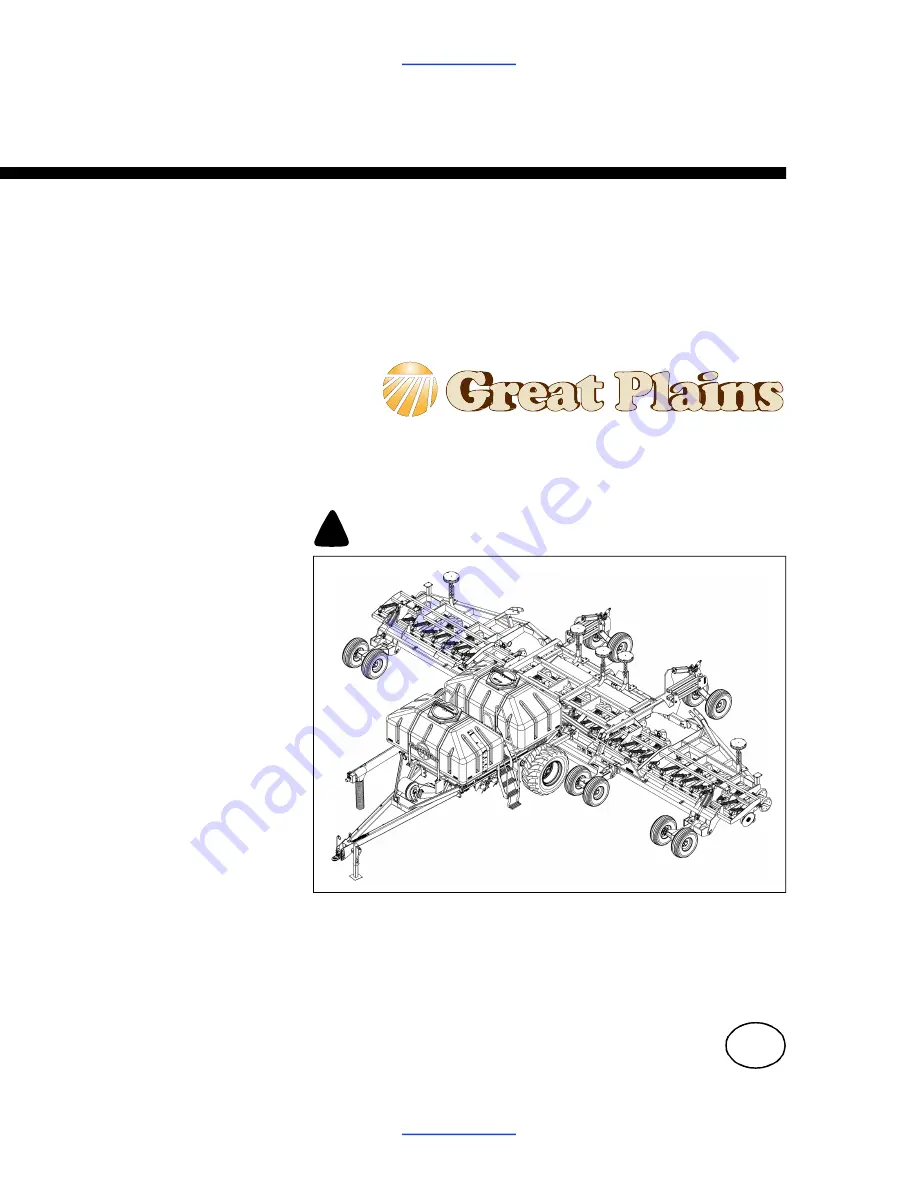
Cover illustration may show optional equipment not supplied with standard 

units.

!

28450

Summary of Contents for NTA3010

Page 1: ...Delivery Manual NTA3010 NTA3510 and ADC No Till Air Drill and Air Drill Cart Read the pre delivery manual entirely When you see this symbol the subsequent instructions and warnings are serious follow without exception Your life and the lives of others depend on it Cover illustration may show optional equipment not supplied with standard units 28450 ...

Page 2: ...able of Contents Important Safety Information 1 Introduction 4 Implements Covered 4 Document Family 4 Definitions 4 Further Assistance 4 Air Cart Pre Delivery 5 Air Cart Preparation 5 Cart Assembly Summary 5 Tools Required 5 ADC2350 Cart Pre Assembly Checklist 5 Unload Air Cart 6 Lift Air Cart on Truck 7 Locate Parts 7 Install Wheels 8 Cart Closeout 8 Install Cab Components 8 Air Drill Assembly 9 ...

Page 3: ...Signal words designate a degree or level of hazard seriousness DANGER indicates an imminently hazardous situation which if not avoided will result in death or serious injury This signal word is limited to the most extreme situations typically for machine components that for functional purposes cannot be guarded WARNING indicates a potentially hazardous situation which if not avoided could result i...

Page 4: ...ece of paper or cardboard NOT BODY PARTS to check for suspected leaks s Wear protective gloves and safety glasses or goggles when working with hydraulic systems s If an accident occurs seek immediate medical attention from a physician familiar with this type of injury Check for Overhead Lines Drill markers contacting overhead electrical lines can introduce lethal voltage levels on implement and tr...

Page 5: ... reflectors or flags to mark implements in case of breakdown on the road s Keep clear of overhead power lines and other obstructions when transporting Refer to transport dimensions under Specifications and Capacities in Operator manual Practice Safe Maintenance s Understand procedure before doing work Use proper tools and equipment Refer to this manual for additional information s Work in a clean ...

Page 6: ... 167 085P ADC2350 2350B Parts Manual 167 085B ADC2350 2350B Seed Rate Manual 110011445 DICKEY john Air Cart Operator 110011460 NTA QUICKSTART GUIDE For ADC2220 167 073M ADC2220 Operator Seed Rate Manual 167 073P ADC2220 Parts Manual 167 088M ADC2220 Pre Delivery Manual Definitions Paragraphs in this format present a crucial point of information related to the current topic Read and follow the dire...

Page 7: ... Hitch to air drill implement Tools Required A tractor adequate for positioning the air cart Tractor requirements for drill pre delivery are more demanding see drill Operator manual A large hoist or two forklifts with a net lifting capacity of 9000 pounds 4082 kg Jacks jack stands or blocks and safety chain General hand tools ADC2350 Cart Pre Assembly Checklist Read and understand Important Safety...

Page 8: ...n elevated air cart and where two fork lifts can approach the cart from each side 2 Use fork lifts or hoists to remove everything except the air cart from the truck This will include wheels for the air cart and may include crates of drill parts and un installed options Do not install any components on the air cart while still on the truck Figure 1 Air Cart on Truck 28207 Have at least four people ...

Page 9: ...either side of the ladder and as far forward on the air cart as possible This places the front fork F as close to the tongue joint as possible and places the back fork B as close to the ladder as possible 2 Secure both forks to the frame tube with cargo straps 3 Lift the cart about a foot 30cm 4 Signal the driver to pull the truck away 5 Lower the cart to the ground Locate Parts Review the Parts L...

Page 10: ...e rear of the frame with jack stands 2 Remove and save the nuts 20 total 803 183C NUT HEX FLANGE 3 4 16 PLT from the rear hub assemblies 3 Select one 168 381K 23 5 55 26 TIRE 20 10BLT WL LH Mount the wheel valve stem side out on the left hand side of the cart Secure with ten nuts 4 Select one 168 380K 23 5 55 26 TIRE 20 10BLT WL RH Mount the wheel valve stem side out on the right hand side of the ...

Page 11: ... Operator s Manual A hoist or forklifts with a total capacity of 11 000 pounds 4990 kg for removing components from truck and for assembly Jacks jack stands or blocks and safety chain General hand tools including snap ring pliers About 14 gallons 53 liters of hydraulic fluid to charge the cart and implement systems Drill Pre Assembly Checklist Read and understand Important Safety Information on pa...

Page 12: ...rhead lines particularly if the drill will have markers The air cart requires at least 12ft 7 6m vertically and more if auger deployment is contemplated Crushing hazard You may be severely injured or killed by the implement frames if they fall Always support the frame sections with jack stands or blocks before working on implements raised off the ground Obey all safety instructions from lifting eq...

Page 13: ...parate truck Note The heaviest sub assemblies may weigh as much as 11 000 pounds 4900 kg 1 Remove the frame sections from the truck and place them on the ground The wings are stacked together 2 Disconnect the wings Support top wing with the hoist or forklift and remove the u bolts that hold the top wing shipping stands to the bottom wing Leave the shipping stands on the wings 3 Carefully lift the ...

Page 14: ... pivot bushings 890 011C BUSHING SPINDLE 1 1 2X1 1 4X1 are in place in the three rockshaft pivot tubes 2 At each center section clevis drive out and save 805 249C PIN ROLL 3 8 X 2 PLT then remove and save three 160 201H WING PIVOT PIN WELDMENT 3 With hoist or forklift move the rockshaft 161 074H NTA 35 ROCKSHAFT WELDMENT to the front of the implement and align each rockshaft pivot tube with the ce...

Page 15: ...e wheel arm 161 076H NTA WING GAUGE WHEEL WLDMNT RH to the front of the right hand wing Determine which gauge wheel arm is for the current wing by looking at the cylinder lug on the wheel arm When standing behind the arm pivot tubes the lug will be to the outside right of center for the right hand wing and left of center for left hand wing 4 Align wing clevis and arm pivot tubes When in place righ...

Page 16: ...a reinforcing ring on each wheel Insert bolts and tighten to torque specification 4 Repeat step 1 through step 3 for the right hand side of the rockshaft Mount Front Gauge Wheels Start with the left hand gauge wheel Refer to Figure 9 1 At the two gauge wheel hubs remove and save 12 gauge wheel bolts 802 104C BOLT WHEEL 1 2 20X1 90 DEG Do not mix bolts Although all wheel bolts are 1 2 20 thread win...

Page 17: ...olt lock washer and nut 4 Repeat step 1 through step 3 for the right hand lift assist assembly Mount Wheels on Casters Refer to Figure 11 There are two assemblies and four wheels 1 At the caster assemblies 161 116K NTA35 DUAL CASTER WHEEL ASSY remove and save 12 caster wheel bolts 802 104C BOLT WHEEL 1 2 20X1 90 DEG Do not mix bolts Although all wheel bolts are 1 2 20 thread lift assist caster whe...

Page 18: ... 1 4 GR5 804 015C WASHER LOCK SPRING 1 2 PLT and one 161 231D NTA CASTER RETAINER CAP 2 Use forklift or hoist to raise lift assist arm caster mount Make sure thrust washer is still on caster assembly Roll caster under mount and lower mount onto caster 3 Place retainer cap back on top of caster shaft Secure with bolts and lock washers Tighten to torque spec 4 Repeat step 1 through step 3 for right ...

Page 19: ...save the base end pin hardware 805 017C PIN COTTER 3 16 X 1 3 4 PLT 804 029C WASHER FLAT 1 SAE 805 239C PIN CLEVIS 1 X 3 5 16 HRD PLT 3 With the hydraulic ports facing up or inward pin the base end of the cylinder to the right hand wing eyebolt Secure with clevis pin washer and cotter pin Hoses are routed at step 7 4 Remove and save the rod end pin hardware 805 017C PIN COTTER 3 16 X 1 3 4 PLT 804...

Page 20: ...r assembly Cylinders are identical for both sides Refer to Figure 13 1 At the center section untie the lift assist cylinders Select one 810 333C CYL REP 4 5X12X1 5 ROD 22 25L The gauge wheel cylinders for the wings are labeled 41 2in bore re phasing 2 Remove and save the base end pin hardware 805 017C PIN COTTER 3 16 X 1 3 4 PLT 804 029C WASHER FLAT 1 SAE 805 124C PIN CLEVIS 1 X 3 11 16 GR5 PLT 3 ...

Page 21: ... do not rub against sharp edges and cannot be pinched or crushed by moving parts Allow enough slack at wing gauge wheels for normal lift lower operation and for elevating cylinder rod end during hydraulic charging 9 Check that lift assist hoses do not rub against sharp edges and cannot be pinched or crushed by moving parts Allow enough slack at wing gauge wheels for normal lift lower operation and...

Page 22: ...lts 5 Re insert the lug pins and secure with roll pins 6 Release the tractor brakes and back up the cart until the telescoping arm pins can be inserted and secured with cotter pins Hitching ADC2220 Cart Refer to Figure 18 7 Use a line not shown from the cart walkboard to tie the cart links up so that the ball swivels are at about the same height as the lug holes 8 Drive the roll pins out of the lu...

Page 23: ...the cart 4 Secure cables so they are clear of moving parts at the hitch Continue at Make Hydraulic Connections on page 22 Note After market markers may later require additional electrical connections not listed here ADC2220 Electrical Connection The standard ADC2220 has a single harness connection Refer to Figure 20 1 Connect the drill harness to the receptacle at the right hand end of the hydraul...

Page 24: ...th a low pressure sump return line The standard circuits power lift fold and weight transfer functions An optional circuit operates the markers 1 Remove male fittings from hydraulic quick couplers on the rear of the cart Screw the male ends onto the implement hydraulic hoses If you will not be installing markers store the male QD fittings with the drill for future use Do not leave them in the QD p...

Page 25: ...g oil and possible seal damage with high flow tractors 5 With the tractor engine at idle speed energize the lift hydraulics When the gauge wheel cylinders on both wings are extended completely hold the remote lever on for one minute Check all hydraulic hoses cylinders and fittings for leaks 6 Retract the cylinder rods Extend the rods again and hold the remote lever on for one more minute Repeat th...

Page 26: ...ort locks from storage locations on weldment forward of parallel arms Refer to Figure 25 3 Pin the locks on the extended lift assist cylinder rods 4 If this is the first time the drill has been raised remove the shipping stands Make sure transport locks are in place before removing shipping stands You may be severely injured or killed by being crushed from a falling implement Always have transport...

Page 27: ... glasses or goggles when working with hydraulic systems If an accident occurs seek immediate medical attention from a physician familiar with this type of injury Refer to Figure 26 2 Remove shipping restraints from the fold cylinders at the front of the center section 3 Block wire or otherwise safely support rod ends so that they cannot contact any objects when fully extended Failure to block cyli...

Page 28: ...ulics are fully charged and bled of air page 23 if there is any air in the system or the system has not recently been re phased you will not get correct level 2 Unfold and raise the drill Remove lock channels Set the depth control stop valve to stop the drill in lowering just before the coulters touch the ground Check Center Height Refer to Figure 29 Lay a straight edge across the top of the two c...

Page 29: ... gauge wheel axle 2 If the wing height is the same or less then than 3 16in 5mm different no adjustment is necessary Continue at step 1 If adjustment is indicated continue at step 1 Adjust Wing Height Refer to Figure 31 1 Loosen the upper jam nut 2 Rotate the lower adjuster nut until the wheel height matches the center section 3 Repeat step 1 through step 2 for the other wing Figure 30 Check Wing ...

Page 30: ... to the ground 2 Measure from the bottom of the rear main tool bar to the ground Refer to Figure 33 3 If the rear height is more than 3 16in 5mm different loosen the jam nuts at the rear lift assist eyebolts and turn the adjust nuts until the height matches the front Check height at each side and keep rear level side to side Re tighten jam nuts Figure 32 Front to Back Frame Height 28461 U D B F 3 ...

Page 31: ... PLT 803 020C NUT HEX 1 2 13 PLT Tower Positioning Refer to Figure 35 1 Loosen the two U bolts that hold the tower on the support bracket 2 Reposition the tower so the bottom of the lower round plate is about 203 4in 52 7cm above the frame Turn the inlet tube toward the center of the implement 3 After towers have been installed and before any seed hoses are installed slowly fold the implement whil...

Page 32: ...Tower Approximate Hose Length 1 290in 737 cm 4 290in 737 cm 2 169in 429 cm 5 169in 429 cm Figure 36 NTA3010 Towers and Primary Seed Hoses 16899 F B R L 77 5 cm 77 5 cm 62 Tower Approximate Hose Length Tower Approximate Hose Length 1 274in 696 cm 4 152in 386 cm 2 152in 386 cm 5 274in 696 cm 3 132in 335 cm Figure 37 NTA3510 Towers and Primary Seed Hoses 16201 F B R L 17 8 cm 17 8 cm 62 ...

Page 33: ... 38 4 Select one 800 180C 2 1 2 AIR HOSE BAND CLAMP Slide band clamp over implement end of hose then slide hose at least two inches onto tower inlet Allow enough hose slack so that implement raising lowering folding and unfolding will not pinch or bind hose 5 Using a hacksaw cut hose so it slides at least two inches onto meter outlet 6 Select one 800 180C 2 1 2 AIR HOSE BAND CLAMP Slide band clamp...

Page 34: ...0th Opener 3 Measure the expected hose length and mark hose with grease pencil or tape 4 At the Tower loosen but do not remove perimeter bolts holding tower halves together 5 Insert hose into the current Port Push hose into port until seated against the stop 6 Route hose over implement frame as shown in the Figure that accompanies your Port Assignment table Route seed hoses to prevent rubbing on s...

Page 35: ...e 11 Repeat step 2 through step 10 for each Port on the current Tower working clockwise around the tower 12 When hoses have been installed in all ports tighten bolts on the tower assembly to secure hoses 13 Repeat step 2 through step 12 for each Tower moving right When all hoses have been installed check that seed hoses are long enough for wing flex and short enough to prevent hose damage Hoses ma...

Page 36: ...70cm Port 1 Row 14 62in 157cm Port 2 Row 13 73in 185cm Port 3 Row 11 86in 218cm Port 4 Row 10 69in 175cm Port 5 Row 12 59in 150cm Port 6 Row 15 60in 152cm Port 7 Row 16 66in 168cm Port 8 Row 18 60in 152cm Port 9 Row 17 Tower 3 64in 163cm Port 1 Row 23 61in 155cm Port 2 Row 21 62in 157cm Port 3 Row 19 62in 157cm Port 4 Row 20 61in 155cm Port 5 Row 22 63in 160cm Port 6 Row 24 66in 168cm Port 7 Row 2...

Page 37: ...8cm Port 3 Row 13 81in 206cm Port 4 Row 14 70in 178cm Port 5 Row 16 63in 160cm Port 6 Row 18 62in 157cm Port 7 Row 20 62in 157cm Port 8 Row 22 64in 163cm Port 9 Row 24 60in 152cm Port 10 Row 23 59in 150cm Port 11 Row 21 63in 160cm Port 12 Row 19 Tower 3 62in 157cm Port 1 Row 33 63in 160cm Port 2 Row 29 59in 150cm Port 3 Row 27 64in 163cm Port 4 Row 25 63in 160cm Port 5 Row 26 59in 150cm Port 6 Row...

Page 38: ...Port 4 Row 10 99in 251cm Port 5 Row 11 103in 262cm Port 6 Row 12 95in 241cm Port 7 Row 13 71in 180cm Port 8 Row 16 Tower 3 61in 155cm Port 1 Row 23 71in 180cm Port 2 Row 24 60in 152cm Port 3 Row 21 59in 150cm Port 4 Row 19 62in 157cm Port 5 Row 17 61in 155cm Port 6 Row 18 58in 147cm Port 7 Row 20 59in 150cm Port 8 Row 22 Tower 4 72in 183cm Port 1 Row 26 68in 173cm Port 2 Row 25 84in 213cm Port 3 R...

Page 39: ...21 68in 173cm Port 10 Row 22 76in 193cm Port 11 Row 20 Tower 3 65in 165cm Port 1 Row 32 61in 155cm Port 2 Row 30 61in 155cm Port 3 Row 28 62in 157cm Port 4 Row 24 70in 178cm Port 5 Row 23 64in 163cm Port 6 Row 25 57in 145cm Port 7 Row 26 60in 152cm Port 8 Row 27 62in 157cm Port 9 Row 29 64in 163cm Port 10 Row 31 77in 196cm Port 11 Row 33 Tower 4 81in 206cm Port 1 Row 38 88in 224cm Port 2 Row 37 79...

Page 40: ... the switch Switch mount screws may need to be reversed to point wire down Rubber O rings on the screws must be installed on either side of the switch housing The whisker should extend over the upper parallel arm enough so that the whisker cannot slip off the arm when the drill is lowered but not so far it bends severely To adjust loosen the bolts attaching the switch to the bracket and slide the ...

Page 41: ...ings 17 Select one each 802 421C HFS 1 2 13X3 3 4 GR5 SPTHD 803 169C NUT HEX FLG LOCK 1 2 13 PLT Align the press wheel assembly with the pivot hole in the opener frame Secure with bolt and lock nut 18 Repeat step 16 and step 17 for each rear wing row Install Options Blockage Detectors Blockage detectors are not factory installed as they are mounted after the secondary hoses are installed Install t...

Page 42: ...X 2 525 830 1150 1 12 370 955 1350 M30 X 3 5 960 1510 2100 11 8 7 480 1080 1750 M30 X 2 1060 1680 2320 11 8 12 540 1210 1960 M36 X 3 5 1730 2650 3660 11 4 7 680 1520 2460 M36 X 2 1880 2960 4100 11 4 12 750 1680 2730 13 8 6 890 1990 3230 a in tpi nominal thread diameter in inches threads per inch 13 8 12 1010 2270 3680 b N m newton meters 11 2 6 1180 2640 4290 11 2 12 1330 2970 4820 c mm x pitch no...

Page 43: ... 161 246D NTA CASTER ARM SPACER TUBE 168 216H DISTRIBUTION TOWER WELDMENT 168 362D NTA35 DIST TOWER MOUNT 196 142H EYEBOLT WELDMENT 198 137D PRESS WHEEL PIVOT TUBE 800 180C 2 1 2 AIR HOSE BAND CLAMP 802 034C HHCS 1 2 13X1 1 4 GR5 802 104C BOLT WHEEL 1 2 20X1 90 DEG 802 131C HHCS 5 16 18X3 GR5 802 399C HFS 1 2 20X1 1 2 GR5 802 421C HFS 1 2 13X3 3 4 GR5 SPTHD 802 638C HHCS 1 8X12 1 4 GR8 803 020C NU...

Page 44: ...73P ADC2220 Parts Manual 160 210H NTA CARTLINK WELDMENT 70 71 72 73 Callout Part Number Description 110011445 ACC USR MANUAL 4 VER 2 X SOFTW 110011460 NTA QUICKSTART GUIDE 167 085B ADC2350 2350B Seed Rate Manual 167 085M ADC2350 2350B Operator Manual 167 085P ADC2350 2350B Parts Manual 160 022H PULL LINK WELDMENT 160 023H PULL BAR WELDMENT 168 380K 23 5 55 26 TIRE 20 10BLT WL RH 168 381K 23 5 55 2...

Page 45: ...Bolt OPNR Opener CPC Circular Plastic Connector PLT Plated DD Double Disk PVT Pivot DEG Degree REP Re phasing DJ DICKEY john RH Right Hand FT Feet SAE Society of Automotive Engineers std GR5 Grade 5 SOFTW Software GR8 Grade 8 SPDT Single Pole Double Throw HEX Hexagonal 6 sided SPTHD Special Thread HFS Hex Flange Screw W with HHCS Hex Head Cap Screw Bolt WHL WL Wheel HRD Hardened X by ID Inside Dia...

Page 46: ...Table of Contents Table of Contents ...

Page 47: ...Great Plains Mfg 1525 E North St P O Box 5060 Salina KS 67402 ...

Reviews: