GRAUPNER GmbH & Co. KG D-73230 KIRCHHEIM/TECK GERMANY
Keine Haftung für Druckfehler. Technische Änderungen vorbehalten! Liability for printing errors excluded. We reserve the right to introduce modifications. Sous réserve de modifica-
tions! Nous ne sommes pas responsables d’éventuelles erreurs d’impression!
#0059054
04/2008
15
•
We recommend that you should also apply a drop of oil to the rollers on which the daughter boat runs, to
ensure that they rotate freely. A small drop of oil at the stern flap bearings can do no harm.
Assembling the model
•
Carefully unpack the models and the boatstand.
•
Remove the daughter boat from the cradle; the method of installing the RC components in the smaller
model is described separately in these instructions.
•
The method of connecting the various leads to the receiver is shown in schematic form in the wiring
diagrams which are provided for both models. We assume that you are using the recommended receiv-
ers (R700 for the cruiser, R600 light for the daughter boat). If you prefer to use different types, you must
ensure that no channels are duplicated at the two receivers, as this would make it impossible to control
the models separately.
•
Place the models on the stands provided and leave them there whilst carrying out all the procedures
described below.
Cruiser
•
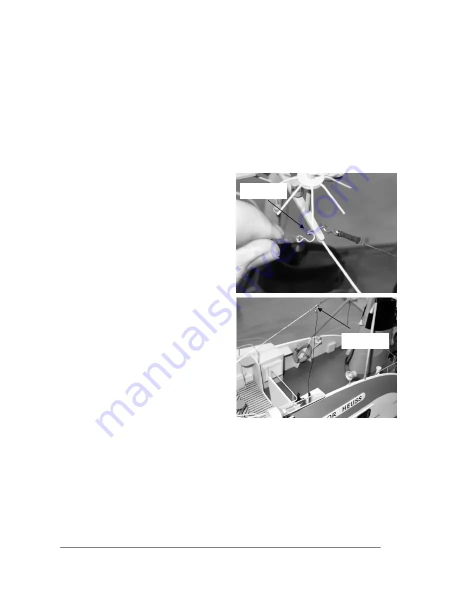
Cautiously disconnect the aerial link wire as
shown, then disconnect the four aerial wires at
the mast. The superstructure can now be care-
fully lifted up and off.
•
Solder a G2 plug to the wires attached to the
centre motor, then solder a G2 plug to each of
the two outer motors, referring to the wiring dia-
gram on page 9 (+ is red (light in the drawing), -
is black). Ensure that the motors spin in the cor-
rect direction: when the battery is connected, the
propellers should rotate in such a way that the
model would be propelled forward.
NOTE
: the
raised lug on the plastic housing of all G2 con-
nectors should always be the positive terminal
(red wire). If you keep consistently to this princi-
ple, your batteries and speed controllers will be
interchangeable, and the system will be protected
against accidental reversed polarity. To make it
easier to solder the plug, it is advisable to use
one of the following methods, as this will reduce
the likelihood of damaging the model with the
soldering iron.
METHOD 1:
remove the motors
from the model by first undoing the grubscrews in
the shaft couplings (motor side only). Undo the
motor screws in the retaining straps - don’t re-
move them completely - and withdraw the mo-
tors. The motors can later be re-installed simply
by reversing the sequence of operations stated
above.
METHOD 2:
use a “third hand” (a special
positionable part-holding tool) to hold the plug,
and use the soldering iron directly inside the hull
(see photo).
Disconnect
Disconnect


