Starlet 50
22
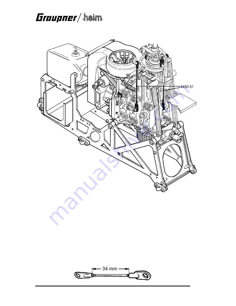
The next stage is to link the swashplate servos to the swashplate using the pushrods already
prepared, to form a 120° linkage.
A four-point swashplate linkage is also possible; details of this alternative installation are left up
to the builder. In this case one further servo is installed in the vacant servo aperture in the
mechanics, and connected to the appropriate linkage point on the swashplate by means of a 2.5
mm Ø pushrod, which has to be angled to suit. The pushrods from servos 2 and 3 are then
connected to the lateral (90°) linkage points on the swashplate. You will need to activate a four-
point swashplate mixer at the transmitter.
If you decide to install a four-point linkage, it is very important to adjust the pushrods really
accurately, otherwise the opposed servos may be under constant strain. This is the procedure:
switch on the radio control system and set the collective pitch stick to centre (servo output arms
at 90° to the pushrods). Disconnect one swashplate pushrod. Adjust the three remaining
pushrods until the swashplate is exactly horizontal. The length of the fourth pushrod should now
be adjusted very carefully so that it can be pressed onto the swashplate linkage ball without
moving it, i.e. without straining any other servo.
Make up the throttle pushrod as shown in the drawing, using the threaded rod 4445.84 (2 mm
Ø, 45 mm long) and two ball-links 4618.55; the stated dimension refers to the actual clearance
between the ball-links.


