140
Program description: Telemetry menu
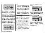
RX SERVO
RX SERVO
REVERSE : OFF
CENTER : 1500µsec
TRIM : –000µsec
LIMIT– : 150%
OUTPUT CH: 01
LIMIT+ : 150%
PERIOD : 20msec
Before you carry out any programming at this screen
display be sure to read the information on page 137.
Value
Explanation
Possible settings
OUTPUT CH Channel select
1 … according to
receiver
REVERSE
Servo reverse
OFF / ON
CENTER
Servo centre in μs If active (high-
lighted), according
to transmitter
control position
TRIM
Trim position in μs
deviating from the
CENTRE position
-120 … +120 μs
LIMIT–
Travel limit on the
“-” side of servo
travel in % servo
travel
30 … 150%
LIMIT+
Travel limit on the
“+” side of servo
travel in % servo
travel
30 … 150%
PERIOD
Cycle time in ms
10 or 20 ms
OUTPUT CH (Channel select)
Select the “Channel” line if necessary using the ar-
row buttons. Touch the
SET
button of the right-hand
touch-key to highlight the value field. Now use the arrow
buttons of the right-hand touch-key to set the desired
channel (e. g. 01).
The following parameters always
refer to the channel which you set at this point:
REVERSE (servo reverse)
Sets the direction of rotation of the servo connected to
the selected control channel: ON / OFF
CENTER (servo centre)
The “CENTRE” line displays the current pulse width in
μs of the control channel selected in the “OUTPUT CH”
line.
The displayed value varies according to the current posi-
tion of the transmitter control which affects this control
channel, and also its trim position.
A pulse width of 1500 μs corresponds to the standard
centre position, and therefore the usual servo centre
setting.
If you wish to alter this value, select the “CENTER” line
and touch the
SET
button. Now move the corresponding
transmitter control, stick and / or trim lever in the desired
direction, and touch the
SET
button again to store the
current position. This position will be stored as the new
neutral position.
TRIM (trim position)
The purpose of the “TRIM” line is to provide fine adjust-
ment of the neutral position of a servo connected to
the control channel selected in the “OUTPUT CH” line.
Adjustments are made in 1 μs increments using the
arrow buttons of the right-hand touch-key. The value
in the “CENTRE” line can be adjusted over the range
+/- 120 μs around the TRIM value set here.
Default setting: 0 μs
LIMIT–/+ (travel reduction, separate for each side)
This option can be used to place a limit on servo travel
(control surface travel) for the servo connected to the
control channel selected in the “OUTPUT CH” line. The
value is set separately for each side of centre.
The setting can be altered separately for both directions
within the range 30 ... 150%.
Default setting: 150% on both sides.
PERIOD (cycle time)
In this line you can determine the frame time for the
individual channel signals. This setting applies to all
control channels.
If you use digital servos exclusively, it is safe to set a
cycle time of 10 ms.
If you are using a mixture of servo types, or exclusively
analogue servos, it is essential to set 20 ms, otherwise
the servos will be “over-stressed” and may response by
jittering or making rumbling noises.
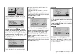
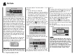
RX FAIL SAFE
RX FAIL SAFE
INPUT CH: 01
MODE : HOLD
F.S.POS. : 1500µsec
DELAY : 0.75sec
OUTPUT CH: 01
FAIL SAFE ALL: NO
POSITION : 1500µsec
Before we describe this menu a few words as a re-
minder:
“Doing nothing” is the worst thing you can do in this
Summary of Contents for mx-12 Hott
Page 1: ...Programming Manual 33116 mx 16 HoTT 3 en mx 16...
Page 35: ...35 For your notes...
Page 49: ...49 For your notes...
Page 55: ...55 For your notes...
Page 59: ...59 For your notes...
Page 63: ...63 For your notes...
Page 69: ...69 For your notes...
Page 91: ...91 For your notes...
Page 101: ...101 For your notes...
Page 123: ...123 For your notes...
Page 181: ...181 For your notes...
Page 193: ...193 For your notes...


