105
Program description - Model type | Winged models
each wing panel for aileron and elevator control.
If you choose “2/4 AIL 2/4 FL”, then aileron and
ele vator are controlled in accordance with the set-
tings in the “Multi-flap” menu; see page 181.
• “8”
This option is intended for models with two eleva-
tor servos. The servo connected to output 8 will
operate in parallel with servo 3 to actuate eleva-
tors. Elevator trim affects both servos.
Note on “8”:
One control, which assigns input 8 by way of the
»
Control adjust
«
menu, is then disconnected from
servo “8” by software for reasons of safety i. e. it is
made ineffective.
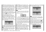
Aileron/camber flaps
After selecting the “Aileron/camber flaps” line with the
selection keys of the left or right four-way button,
the corresponding entry field will be framed:
+100%
SEL
Tail type
Motor at C1
Normal
None
Aile/flaps
1AIL
Model type
Brake Off
In 1
Briefly tap the center
SET
key of the right four-way
button: The current setting will be displayed in inverse
video. Now use the selection keys of the right four-
way button to select the number of wing servos to be
programmed for the model …
… on the
mc-16
transmitter with the standard eight
channels:
No. of wing flaps
Control channel used
1AIL
2
1AIL 1FL
2 | 6
2AIL
2 & 5
Brake offset
This function not only has potential for gliders and
electric models but also for models with combustion
motors and landing flaps.
The mixers described in the “Brake settings” line of
the »Wing mixers« menu, page 183, can be opera-
ted by the C1 stick (“input 1”) or another transmitter
operating element which has been assigned to input
7 or 8 in the »Control adjust« menu in the case of
the standard
mc-16
HoTT eight-channel transmitter.
Inputs 7, 8 or 9 are available for the same purpose on
the
mc-16
HoTT transmitter with the optional twelve
channels, and the standard twelve-channel
mc-20
HoTT transmitter. In this latter case, retain the “GL”
default setting for the “Type” column in the »Control
adjust« menu so the selected control can operate
independent of flight phase.
In the majority of cases the default setting for “input 1”
will remain as it is and the brake will be operated by
way of the non-neutralizing C1 stick.
However, use of input 7, 8 or – if avalaible – 9 makes it
possible to operate the brake in an alternative man-
ner, even by way of a supplementary control, if the C1
stick is to be used for something else.
The neutral point (offset) can be set to any desired
position. This is done by placing the control for input
1, 7, 8 or 9 into the position at which the landing flaps
are to be retracted, i. e. closed, then setting this “Off-
set” point in the column above the column label STO.
The selection of this offset point in this context deter-
mines not only the control position at which the brake
system is to be retracted, i. e. closed, but also the
activation direction of the C1 stick for extending the
brake system.
• Brake offset values with a “+” prefix will cause
flaps affected by the “Brake settings” option of the
»Wing mixers« menu to be extended when the
C1 stick is moved from front to rear, in the direc-
tion of the pilot.
2AIL 1FL
2 & 5 | 6
2AIL 2FL
2 & 5 | 6 & 7
… on the
mc-20
transmitter with twelve channels,
and the
mc-16
transmitter with the optional twelve
channels:
No. of wing flaps
Control channel used
1AIL
2
1AIL 1FL
2 | 6
2AIL
2 & 5
2AIL 1FL
2 & 5 | 6
2AIL 2FL
2 & 5 | 6 & 7
2AIL 4FL
2 & 5 | 6 & 7 / 9 & 10
4AIL 2FL
2 & 5 / 11 & 12 | 6 & 7
4AIL 4FL
2 & 5 / 11 & 12 | 6 & 7 / 9 & 10
Depending on the option selected here, the given
mixers needed and their settings will be activated in
the »Wing mixers« menu, beginning page 183.
Tips:
• Settings for all wing flap pairs (AlL and Al2, FL
and FL2) can be trimmed on a flight-phase basis
in both the »Phase trim« menu as well as in the
Wing mixers« menu, page 183.
• The functionality of all wing flap pairs (AlL and Al2,
FL and FL2) can also be operated by way of the
“Throttle/brake-flap stick” if this stick has not been
assigned to other use, e. g. for certain brake set-
tings, see »Wing mixers« menu, page 183. To
configure this it is only necessary to assign “Con-
trol 1” to input 6 in the »Control adjust« menu,
page 118. (If it is preferable to operate flaps with
switches, one of the transmitter’s two or three po-
sition switches are good for this purpose.)
Summary of Contents for HoTT MC-16 Series
Page 1: ...Programming Manual mc 16 mc 20 HoTT 1 en mc 16 mc 20...
Page 27: ...27 For your notes...
Page 53: ...53 For your notes...
Page 61: ...61 For your notes...
Page 65: ...65 For your notes...
Page 71: ...71 For your notes...
Page 103: ...103 For your notes...
Page 107: ...107 For your notes...
Page 111: ...111 For your notes...
Page 155: ...155 For your notes...
Page 165: ...165 For your notes...
Page 201: ...201 For your notes...
Page 229: ...229 For your notes...
Page 231: ...231 For your notes...
Page 261: ...261 For your notes...
Page 265: ...265 For your notes...
Page 301: ...301 For your notes...
Page 327: ...327 For your notes...
Page 328: ...328 For your notes...


