background image

Agusta A119 Koala

12

When you are confident that everything lines up correctly and is held securely in place, the rear
part of the shells can be glued together in the following areas only:

• 

The top of tail boom along the shaft tunnel, then forward and up to just aft of the main rotor
shaft;

• 

The whole of the upper vertical stabiliser;

• 

The whole tail cone;

• 

The whole of the bottom vertical stabiliser.

Do not allow the glue to run onto other areas, otherwise it may be impossible to install
the mechanics when you have finished!

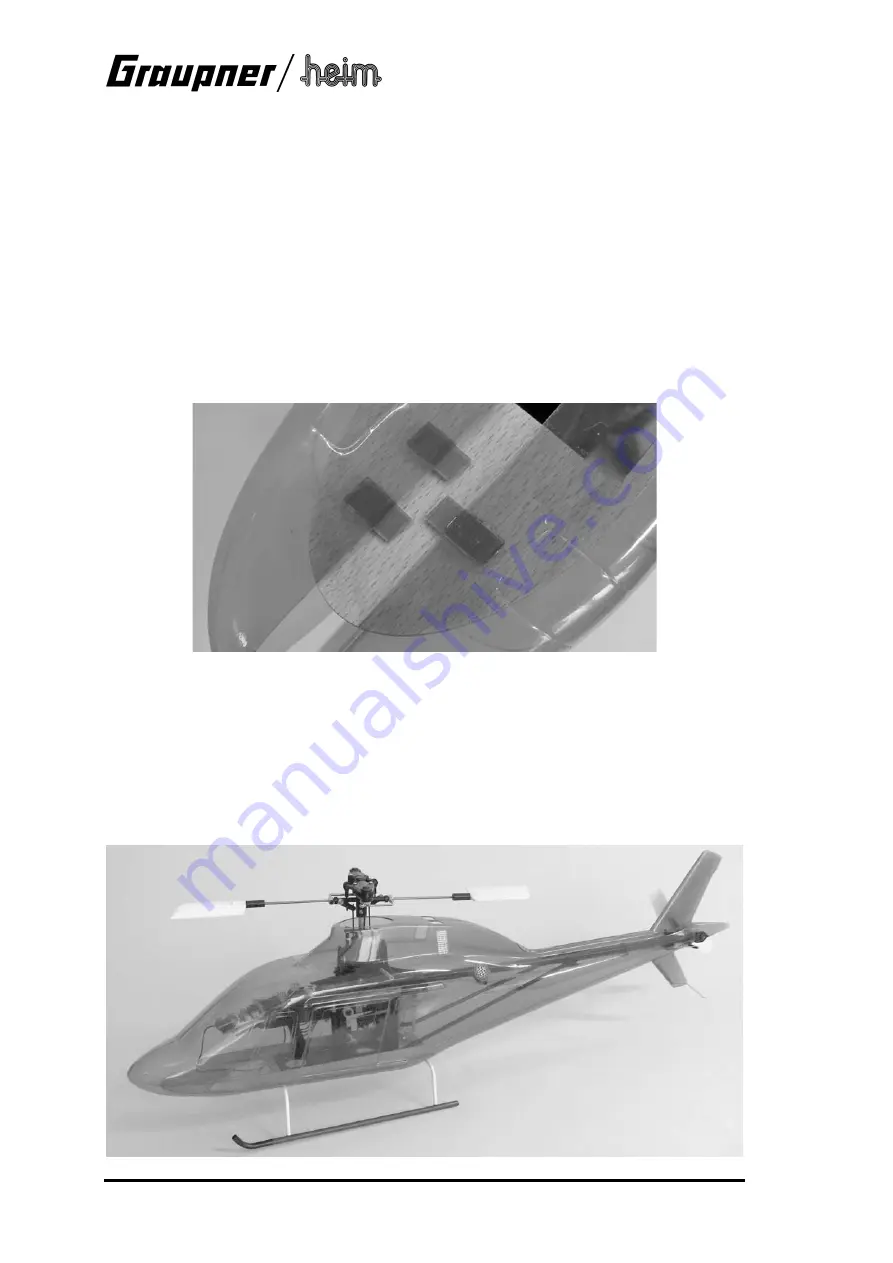
Remove the strips of tape when the glue has set hard. Cut narrow strips of scrap plastic and cut
them into short pieces as shown. Glue these small rectangles along the joint line in the front
section of the fuselage, fitting them in groups of three to form locating tongues: in each case
glue two pieces on the inside of one shell, with a third strip between them on the other side (see
photo). Roughen all joints with abrasive paper before applying the glue.

Final trimming of the fuselage shell

Gently spread the fuselage shells on the underside so that the chassis can be installed from un-
derneath. When you do this it is important to ensure that the tail rotor pushrod exits the fuselage
through the appropriate opening. Check that the fuselage shell is a snug fit all round the chassis
when the shells are held together with a few strips of adhesive tape: the openings at the bottom
should be a close fit round the skid bars, but without placing the fuselage under strain. Check
that the main rotor is free to rotate without any danger that the swashplate, pushrods or other
linkage components could foul the fuselage.

Summary of Contents for Agusta A119 Koala

Page 1: ...licopter but the model is by no means a harmless plaything If assembled incorrectly or handled incompetently or carelessly it can cause serious injury to persons and damage to property You alone are r...

Page 2: ...permanently at the tail end at the front they are held together by strips of adhesive tape so that the chassis can still be removed easily from the fuselage for maintenance work The fuselage is vacuu...

Page 3: ...which are naturally subject to wear including gearbox components motor ball links etc and as a result it is absolutely essential to check and maintain the model regularly It is standard practice with...

Page 4: ...these other parts for the task We have made every effort to point out to you the dangers inherent in operating this model helicopter Since neither we the manufacturer nor the model shop that sold you...

Page 5: ...parts P 18 The instructions We have invested considerable effort in producing these instructions with the aim of ensuring that your model helicopter will fly reliably and safely Please take the troub...

Page 6: ...gyro system Radio control system see main Graupner catalogue We recommend a radio control system equipped with special helicopter options or a micro computer radio control system such as the mc 12 mc...

Page 7: ...d disconnect it from the pushrod Loosen the clamping screws in the tail rotor housing and withdraw the tail rotor housing to the rear Separate the skid landing gear no longer required from the chassis...

Page 8: ...the tubes should be 108 mm apart perfectly square and parallel to each other Remove the skid bars from the skid tubes without disturbing the tubes and slide lengths of 3 2 mm plastic tube onto them t...

Page 9: ...d in place Align the curved ends so that they are parallel to each other and check that they form a neat joint with the carbon fibre tubes Allow the glue to cure fully This completes the landing gear...

Page 10: ...ON OFF switch is easily accessible when the model is complete The upper bodywork stand off pillars consist of a 70 mm length of 2 mm carbon fibre rod Drill a 2 mm hole in both chassis side frames as...

Page 11: ...erve as additional air openings to cool the motor Cut the openings in the underside of the fuselage for the skid bars working along the marked lines In the top of the shells cut out as large an oval o...

Page 12: ...on of the fuselage fitting them in groups of three to form locating tongues in each case glue two pieces on the inside of one shell with a third strip between them on the other side see photo Roughen...

Page 13: ...p flat plastic sheet left over from the fuselage shells The cover can be at tached using a tape hinge and held closed with another strip of tape Horizontal stabilisers Cut out the cambered bottom shel...

Page 14: ...ks provided in the kit Rub down the surfaces to be painted using very fine abrasive paper 600 1200 grit to ensure that the paint adheres well This is particularly important along the joint line if you...

Page 15: ...tem Check that the transmitter and flight batteries are fully charged Do not let the model fly out of safe visual range Post flight checks Clean the model and check that all screws etc are still tight...

Page 16: ...its positional stability is reduced with the result that it tends to break away in an unpredictable direction Climb Any excess power above that required for hovering can be exploited to make the heli...

Page 17: ...then keeps the blades turning The rotational energy stored in the rotor by this means can be converted into upthrust when the helicopter is close to the ground by the pilot applying positive collecti...

Page 18: ...ummy exhaust pipes Clear plastic smoked tint 2 6 Chassis base plate Beech ply approx 240 x 60 x 1 5 1 7 Lateral chassis stiffener Beech ply approx 205 x 12 x 1 5 2 8 In fill piece Balsa 60 x 40 x 6 1...

Reviews: