Zodiak Installation and Service Manual
63
Video Processor Frame Installation
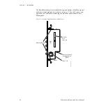
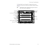
The Zodiak Video Processor frame houses components as shown in
. The Video Processor frame is shown below with the front door
removed.
Note
The front door must remain in place and closed during normal system oper-
ation to maintain maximum cooling efficiency.
Figure 42. Video Processor Frame, Front View
8096_00_16_r2
ON
OFF
Control Processor/DSK/Still Store
(Slot 1)
M/E (M/E 1 & 2)
(Slot 2)
Fan Module
Floppy Drive
M/E (M/E 3)
(Slot 3)
Input/Crosspoint/Sync Generator
(Slot 4)
Power Supply Slots (3)
Air Filter
Air Filter Handle
Fan (4)
on Module
P/S Slot 2
P/S Slot 1
P/S Slot 3
P/S Latch
Single Board
Computer
Mezzanine
Power Switch


