


118
KARRERA K-FRAME — Installation & Service Manual
Section 5 — Basic Configuration
4.
You can assign the component to a suite and control surface now if you
wish, but it is recommended to initially configure your Karrera K-
Frame system as a single suite. Later, you can modify the configuration
for multi-suite operation.
Remote Aux Panel Configuration
Each Remote Aux Panel needs to be configured, which involves identifying
what Aux Bus(es) it will be able to control, and which sources will be avail-
able on that panel’s button. See
Mapping Logical Remote Aux Panels
and
for more informa-
tion.
Control Panel Brightness Adjustment
The Control Panel is calibrated at the factory for even brightness and color
balance. Individual panel area illumination levels cannot be adjusted in the
field. However, the relative brightness of button tally, source name dis-
plays, and text displays can be adjusted on a global basis to meet individual
requirements (for example, to accommodate varying ambient room
lighting levels).
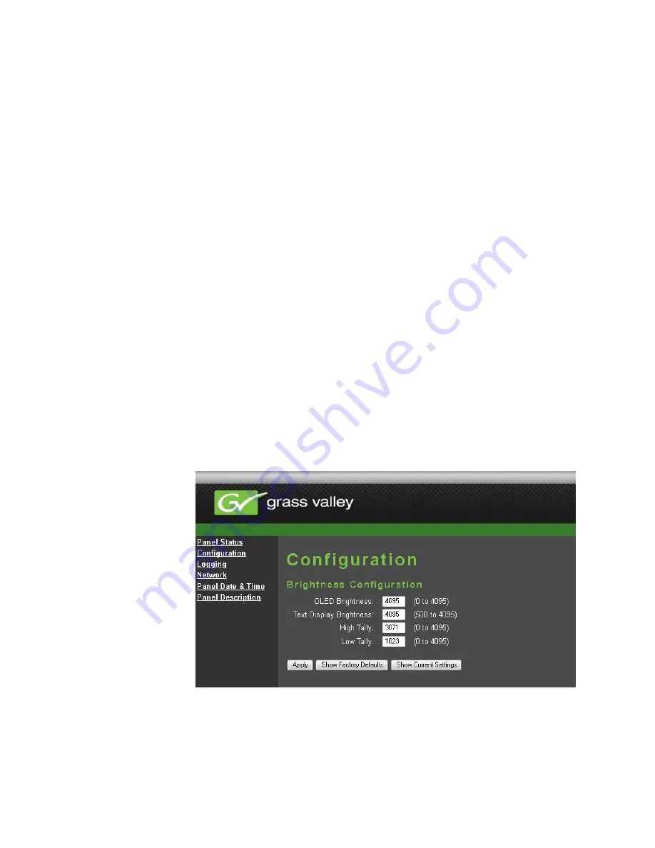
1.
Access the Karrera K-Frame Panel webpage, by entering its IP address
in a web browser, then clicking on
Configuration
(
Figure 82. Control Panel Brightness Adjustment
2.
Enter the desired values for
OLED
,
Text Display
,
High Tally
, and
Low Tally
, and
then click
Apply
.
Summary of Contents for KARRERA K-FRAME
Page 12: ...12 KARRERA K FRAME Installation Service Manual Contents ...
Page 30: ...30 KARRERA K FRAME Installation Service Manual Regulatory Notices ...
Page 56: ...56 KARRERA K FRAME Installation Service Manual Section 2 Control Surface Installation ...
Page 266: ...266 KARRERA K FRAME Installation Service Manual Appendix B Field Replaceable Units ...
Page 278: ...278 KARRERA K FRAME Installation Service Manual Index ...