


8920MUX Instruction Manual
11
Installation
Cabling
Note
At the back of every hard cover manual are overlay cards that can be placed
over the rear connector BNCs to identify the specific 8920MUX connector
functions.
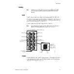
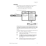
Inputs
The SD video stream is connected to the looping input BNC at J9 or J10.
For balanced audio inputs, use the terminal post adapter shown in
to connect up to two AES/EBU input sources. The adapter connects to the
plus and minus BNC pairs J5/J7 and J6/J8.
Connect unbalanced AES/EBU input BNCs to J5 and J6.
Note
Jumper selections on the module must be made to select either 75
Ω
unbal-
anced or 110
Ω
balanced AES/EBU input (see
).
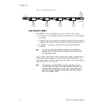
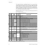
Figure 4.
8920MUX
Input/Output Connectors
Outputs
The 8920MUX provides four SD output streams—J1 through J4. The desti-
nation equipment should have a 75
Ω
input impedance or loop-through
inputs that are terminated into 75
Ω
.
J9 J10
IN
J3
J5
J7
J4
J6
J8
J2
J1
8037-02r1
Loop-through
SD Input
SD Output 1
SD Output 3
AES Input 1
unbalanced 75
Ω
SD Output 2
SD Output 4
AES Input 2
unbalanced 75
Ω
Adapter for
balanced 110
Ω
inputs, connects
to BNCs J5 - J8.
X
O
U
T
J1
J4
R+
GND
R–
L+
GND
L–
Grass Valley
Adapter
AES
Input 1
AES
Input 2
Summary of Contents for 8920MUX -
Page 4: ...4 8920MUX Instruction Manual Contents ...
Page 6: ...6 8920MUX Instruction Manual Preface ...
Page 28: ...28 8920MUX Instruction Manual Configuration Figure 12 Audio Group Management Display ...
Page 32: ...32 8920MUX Instruction Manual Configuration Figure 15 8920MUX Slot Config Page ...
Page 44: ...44 8920MUX Instruction Manual Functional Description ...
Page 48: ...24 8920MUX Instruction Manual 8920MUX Video Audio Multiplexer ...
Page 50: ...24 8920MUX Instruction Manual 8920MUX Video Audio Multiplexer ...