background image


8911 Instruction Manual

3

Speci

fi

cations


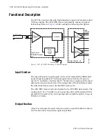
The outputs feed a resistive network that performs three functions:


Attenuates the signal to become 1 volt peak-to-peak,


Creates a 75


 output resistance matching the cable impedance, and


Limits the rise and fall times to meet the AES/EBU speci

fi

cation.


Linear Regulator


The voltage regulator is a monolithic integrated circuit with a 

fi

xed voltage 

output of +5 volts. This regulator employs internal current limiting and 
thermal shutdown.


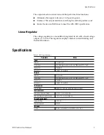
Specifications


Table 1.  8911 Speci

fi

cations


Parameter

Value

Input


Number

1 loopthrough

Signal type

AES/EBU digital audio, per AES3id:1995 and SMPTE 276M

Connector 75


 BNC

Return loss

>25 dB, 0.1 to 6 MHz


Outputs


Number

8 reclocked

Signal type

AES/EBU digital audio, per AES3id:1995 and SMPTE 276M

Connector 75


 BNC

Return loss

>25 dB, 0.1 to 6 MHz


Performance


Sample Rates

48KHz, 44.1KHz, and 32KHz (Automatic selection)


Environmental


Operating temperature range

0 to 45° C, noncondensing

Non-operating temperature range

-10 to +70° C, noncondensing


Power Requirements


Supply Voltage

+12 Volts

Power dissipation

3 Watts


Physical


Frame

Resides in standard 2 rack unit 8900 Series frame

Summary of Contents for 8911 AES-EBU

Page 1: ...8911 A ES EBU RECLOCKING DISTRIBUTION AMPLIFIER Instruction Manual 071 0544 00 FIRST PRINTING JANUARY 1999 ...

Page 2: ...nts issued and pending Product options and specifications subject to change without notice The informa tion in this manual is furnished for informational use only is subject to change without notice and should not be construed as a commitment by Grass Valley Group Grass Valley Group assumes no re sponsibility or liability for any errors or inaccuracies that may appear in this publication Region Vo...

Page 3: ... v 8911 AES EBU Reclocking Distribution Amplifier Introduction 1 Functional Description 2 Input Section 2 Output Section 2 Linear Regulator 3 Specifications 3 Module Installation 4 Cabling 5 Loopthrough Input 5 Outputs 6 Testpoints and Indicators 6 Service 7 Index ...

Page 4: ...iv 8911 Instruction Manual Contents ...

Page 5: ...cribes the features of a specific module of the 8900 Series Distribution Amplifier family As part of this module family it is subject to Safety and Regulatory Compliance described in the 8900 Series frame and power supply documentation see the 8900 Series User s Guide ...

Page 6: ...vi 8911 Instruction Manual Preface ...

Page 7: ...puts high density and a wide range of distribution and format conver sion functions The 8900 Series product line is a family of serial digital distribution ampli fiers DAs and signal processors that reside in a 2 rack unit frame which accommodates up to ten modules A variety of modules are available that can provide fanout timing reclocking monitoring or error detection and handling capabilities M...

Page 8: ...ormer T1 Transformer coupling on the input eliminates common mode noise The output side of the transformer feeds the differential line receiver of AES EBU receiver U3 The AES EBU receiver reclocks the data for its AES EBU data stream The mode pins 17 18 23 and 24 are set to pass the entire AES3 signal with the preamble The receiver has an incoming audio sample frequency range of 25 KHz to 55 KHz O...

Page 9: ...own Specifications Table 1 8911 Specifications Parameter Value Input Number 1 loopthrough Signal type AES EBU digital audio per AES3id 1995 and SMPTE 276M Connector 75Ω BNC Return loss 25 dB 0 1 to 6 MHz Outputs Number 8 reclocked Signal type AES EBU digital audio per AES3id 1995 and SMPTE 276M Connector 75Ω BNC Return loss 25 dB 0 1 to 6 MHz Performance Sample Rates 48KHz 44 1KHz and 32KHz Automa...

Page 10: ...the Controller module This module provides the interface for the forced air cover as well as the SMPTE 269M fault reporting health alarm For additional information concerning the Controller module refer to the Controller manual Figure 2 8900 Series Frame To install a module into the frame follow these steps 1 Insert the module into the frame connector end first with component side of the module fa...

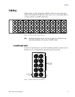
Page 11: ...r J10 See Figure 4 Terminate the unused connector into 75Ω Figure 4 Typical Module Input and Outputs J1 J2 J3 J4 J5 J6 J7 J8 J9 J10 IN DA1 J2 J4 J6 J8 J1 J2 J3 J4 J5 J6 J7 J8 J9 J10 IN DA3 J1 J2 J3 J4 J5 J6 J7 J8 J9 J10 IN DA5 J1 J2 J3 J4 J5 J6 J7 J8 J9 J10 IN DA2 J1 J2 J3 J4 J5 J6 J7 J8 J9 J10 IN DA7 J1 J2 J3 J4 J5 J6 J7 J8 J9 J10 IN DA9 J1 J2 J3 J4 J5 J6 J7 J8 J9 J10 IN DA4 J2 J4 J6 J8 J1 J2 J3 ...

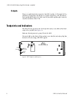
Page 12: ...e the unused loopthrough connector must be terminated into 75 Ω Testpoints and Indicators The 8911 DA has ground and 5V testpoints easily accessible on the front edge of the module see Figure 5 Between the testpoints is a green Power On LED The Lock LED on the front of the module is on when the reclocking chip has locked on the incoming AES EBU signal Figure 5 8911 Testpoints and Indicators 8911 A...

Page 13: ...ignal present LED Check input signals Check cables and connections Verify that source equipment is operating correctly Check output connections Refer to Figure 5 for supply voltage test points on the 8911 module If the module is still not operating correctly replace it with a known good spare and return the faulty module to a designated Grass Valley repair depot Call your Grass Valley representati...

Page 14: ...8 8911 Instruction Manual 8911 AES EBU Reclocking Distribution Amplifier ...

Page 15: ...ntal 3 F frame 4 functional description 2 I impedance connectors 6 indicators 6 input loopthrough 5 specification 3 M module installation 4 O outputs 5 connectors 6 specification 3 termination 6 P performance 3 power requirements 3 power supply 4 R repair depot 7 S specifications 3 T termination 5 testpoints 6 7 troubleshooting 7 ...

Page 16: ...Index 2 8911 Instruction Manual ...

Reviews: