


6028 Series Quick Setup Guide
3
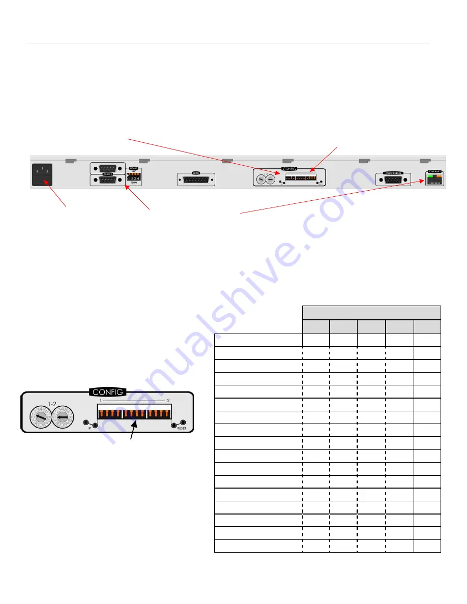
Configuration and Connection
Step 1: Select Control System
Control panel modes are set using DIP switch 6. See table below:
LCD Control Panel Modes
Note:
Mode must match database configuration. A mismatch is not flagged – switches may still light and
control router crosspoints.
DIP
Switches
5
6
7
8
9
16
Way
BPX
Up
Up
Up
Up
Up
Dual
8
Split
BPX
Down
Up
Up
Up
Up
8x8
X
‐
Y
Up
Down
Up
Up
Up
16x4
X
‐
Y
(no
level
keys)
Down
Down
Up
Up
Up
32
Way
BPX
Up
Up
Down
Up
Up
Dual
16
Split
BPX
Down
Up
Down
Up
Up
16x16
X
‐
Y
Up
Down
Down
Up
Up
32x4
X
‐
Y
(no
level
keys)
Down
Down
Down
Up
Up
48
Way
BPX
Up
Up
Up
Down
Up
Dual
24
Split
BPX
Down
Up
Up
Down
Up
48x4
X
‐
Y
(no
level
keys)
Down
Down
Up
Down
Up
32x16
X
‐
Y
Up
Up
Down
Down
Up
Dual
16+16
BPX
Down
Up
Down
Down
Up
16x16
X
‐
Y
Up
Down
Down
Down
Up
24x12
X
‐
Y
Down
Down
Down
Down
Up
User
Defined
Up
Up
Up
Up
Down
Step 3: Connect Power
Plug cable into 2A fused IEC
socket
Step 1: Select Control System
LED control panel modes are set using DIP switches 5 – 9. See table below
LCD control panel modes are set using DIP switches 1
UP = 6711 Mimic (BPX or Freeform)
Step 2: Select Comms Type
Set DIP switch 10:
UP = RS485 (serial)
DOWN = Ethernet
Step 4: Setup Comms
Connect the appropriate cable to a comms port (serial or Ethernet) and configure the port address
-
Standard RS232/485 pinout Serial Cable
-
Standard CAT-5 10/100 BASE-T straight-through or crossover Ethernet cable
Set DIP switches 5 – 9
According to the table to set
the control panel
DIP Switches


