FC4200-UM-251-03-9370
35
ELECTRICAL SECTION
7.2 Writing to Flash Memory
To update the system frmware you need to have the following files. In addition, you need to use a com-
puter.
Firmware
:FC4200-50 / 60 or FC4210
SEND.EXE
:Utillity to transfer files using Windows
SENDB.EXE :Utillity to transfer files using DOS
1. Check that the power supply (J14) and control panel unit (J10) are connected to the main board.
Connect a personal computer to the Centronics terminal (J18).
Caution:
If you are writing to a new board for the first time, remove the motor and flex cable connectors before
performing the write.
2. Set the DIP switch to “Normal mode” or “Adjustment mode.”
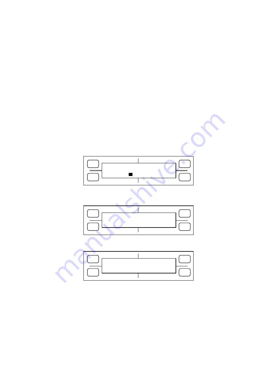
3. Hold down both the “Right” and “Left” POSITION keys while turning on the power. When you hear a short
buzzer tone, release the keys. The LCD should display the following:
FORCE
SPEED
OFFSET
QUALITY
F1
F3
F4
F2
INPUT PASSWORD
4. Press the POSITION keys in the sequence “Up”, “Down”, “Right” and “Left”. A buzzer will sound, and the
LCD will display the following:
FORCE
SPEED
OFFSET
QUALITY
F1
F3
F4
F2
SELECT SEND MODE
GET-ACK ACK-GET
Press [F2] or [F4] depending on the type of computer you are using. (Normally, press [F2].)
The display changes to display the following:
FORCE
SPEED
OFFSET
QUALITY
F1
F3
F4
F2
PLEASE SEND PROGRAM!
PLOTTER (GET-ACK)
Summary of Contents for FC4200-50
Page 1: ...FC4200 UM 251 03 9370 CUTTING PLOTTER SERVICE MANUAL MANUAL NO FC4200 UM 251...
Page 79: ...FC4200 UM 251 03 9370 74 PART LIST External Casing...
Page 81: ...FC4200 UM 251 03 9370 76 PART LIST Main Frame X Slide Section and X Drive Section...
Page 82: ...FC4200 UM 251 03 9370 77 PART LIST X Rear Slide Section for FC4210 60 14 15 23 24 21 22 20...
Page 87: ...FC4200 UM 251 03 9370 82 PART LIST Registration Mark Sensor Section for FC4210 60 39 17...
Page 89: ...FC4200 UM 251 03 9370 84 PART LIST Electrical Section...
Page 93: ...FC4200 UM 251 03 9370 88 CIRCIT DIAGRAMS 12 2 Main Board Main Board 1 10...
Page 94: ...FC4200 UM 251 03 9370 89 CIRCIT DIAGRAMS Main Board 2 10...
Page 95: ...FC4200 UM 251 03 9370 90 CIRCIT DIAGRAMS Main Board 3 10...
Page 96: ...FC4200 UM 251 03 9370 91 CIRCIT DIAGRAMS Main Board 4 10...
Page 97: ...FC4200 UM 251 03 9370 92 CIRCIT DIAGRAMS Main Board 5 10...
Page 98: ...FC4200 UM 251 03 9370 93 CIRCIT DIAGRAMS Main Board 6 10...
Page 99: ...FC4200 UM 251 03 9370 94 CIRCIT DIAGRAMS Main Board 7 10...
Page 100: ...FC4200 UM 251 03 9370 95 CIRCIT DIAGRAMS Main Board 8 10...
Page 101: ...FC4200 UM 251 03 9370 96 CIRCIT DIAGRAMS Main Board 9 10...
Page 102: ...FC4200 UM 251 03 9370 97 CIRCIT DIAGRAMS Main Board 10 10...
Page 103: ...FC4200 UM 251 03 9370 98 CIRCIT DIAGRAMS 12 3 Control Panel Relay Board...
Page 104: ...FC4200 UM 251 03 9370 99 CIRCIT DIAGRAMS 12 4 Y Motor Relay Board...
Page 105: ...FC4200 UM 251 03 9370 100 CIRCIT DIAGRAMS 12 5 Pen Board Pen Board for FC4200 50 and FC4200 60...
Page 106: ...FC4200 UM 251 03 9370 101 CIRCIT DIAGRAMS Pen Board for FC4210 60...


