background image


2635 W. 7

th

 Place, Eugene, Oregon 97402, USA  

9  

Valid from February 2017 


www.grapesolar.com 


9 Tel: 1-877-264-1014 (toll free), 1-541-349-9000, Fax: 1-541-343-9000 


PHOTOVOLTAIC MODULES SAFETY 


AND INST


ALLATION MANUAL Rev. 


P


VALID IN NORTH AMERICA ONLY


4.


Grounding  

4.1


To reduce the possibility of electrical shock and protect the PV system from lightning, all 
module frames and mounting racks must be properly earth grounded by using grounding 
hardware that has been UL-1703 certified and in accordance with the National Electrical Code 
before wiring the circuit.  

4.2


If the building at which the PV system is installed is already equipped with exterior lightning 
protection system, the PV system installation must be integrated in the lightning protection 
system.  

4.3


Each PV module has 2 holes on back frame with grounding sign   . Grape Solar recommends the 
following three methods of grounding the module frame:   

4.3.1


 Facing the back of the module, attach an ILSCO GBL-4DBT ground lug to either  

grounding hole at the back of the module. Place the ground lug on the module frame’s 
outer surface and in-line lengthwise. Insert a #8-32 x 0.5” stainless steel screw through 
the ground lug and frame, and secure from behind with a #10 stainless steel star washer 
and nut. Torque the screw to 25 inch lbs (2.8Nm).  

4.3.2


 Use the UL-1703 listed grounding and bonding equipment (KDER), e.g. SOLKlip type 

1954381-1 by Tyco Electronics Corp (E69905), or WEEB Type, to provide a reliable 
grounding connection to the module frame.  

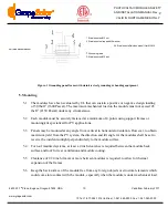
4.3.3


 Use a set of stainless steel grounding and bonding equipment including bolt/nut/cupped 

washer/flat washer/serrated washer to provide a reliable grounding connection to the 
module frame (refer to Figure-1). A flat washer is required between serrated washer and 
Φ2.5mm grounding wire. A cupped washer is required between grounding wire and the 
nut (with torque less than 4N•m). Grounding wire should be directly connected with the 
screw.  


4.4


The rack must also be grounded unless they are mechanically connected by nuts and bolts to the 
grounded PV modules. The array frame shall be grounded in accordance with NEC Article 250.


Summary of Contents for GS-M60-285-Fab1-US

Page 1: ...ies to Grape Solar photovoltaic modules with model number GS P60 265 Fab1 GS P60 265 Fab2 GS S60LSQ 285 PR GS M60 285 Fab1 US and GS M60 300 Fab1 US Carefully read through this manual in its entirety...

Page 2: ...Tel 1 877 264 1014 toll free 1 541 349 9000 Fax 1 541 343 9000 PHOTOVOLTAIC MODULES SAFETY AND INSTALLATION MANUAL Rev P VALID IN NORTH AMERICA ONLY Table of Contents I General Information 3 II Safet...

Page 3: ...land based applications only 6 Rated power output specification of Grape Solar PV modules are made at the Standard Test Condition STC which is 1000W m2 irradiance 1 5 Air Mass AM and 25 C 77 F cell te...

Page 4: ...tore the modules in a dry ventilated in door space if possible If the un connected modules have to be stored outside for any length of time always have the glass surface facing down and cover modules...

Page 5: ...fety Standard for Electrical Installations Canadian Electrical Code Part 1 3 2 Keep children away from module and the system when installing 3 3 Do not wear metallic jewelry while performing mechanica...

Page 6: ...inals can result in burns sparks and lethal shock whether the module is connected or disconnected 3 14 Cover all modules in the PV array with an opaque cloth or material before making or breaking elec...

Page 7: ...t least a 4 inch clearance is required between the module back surface and roof for rear ventilation and module cooling 1 4 The modules have been evaluated by following UL 1703 standard that can susta...

Page 8: ...ained personnel from disconnecting the modules when under load which may cause serious bodily injury or death all Grape Solar PV modules are equipped with factory installed PV wires and MC 4 comparabl...

Page 9: ...DBT ground lug to either grounding hole at the back of the module Place the ground lug on the module frame s outer surface and in line lengthwise Insert a 8 32 x 0 5 stainless steel screw through the...

Page 10: ...ft2 2150 Pascal under any circumstance 5 2 Each module must be securely fastened at a minimum of 4 points using support frames or mounting kits specialized for PV applications 5 3 Panels may be mount...

Page 11: ...steel screw via each mounting hole with stainless steel flat washer and secure from behind with another stainless steel flat washer local washer and nut Torque the bolts to 6 3ft lbs 8 5Nm 5 9 2 Press...

Page 12: ...Solar assumes no liability for loss damage injury or expense arising through improper use or incorrect installation operation or maintenance Furthermore Grape Solar assumes no responsibility for any...

Reviews: