8
REAR VIEW
348
210
70
140
855
688
760
RIGHT SIDE VIEW
200
19
47
25
125
594
766
805
704
17
R/H flow
R/H return
L/H flow
L/H return
LEFT SIDE VIEW
111
566
Flue centre line
Alternative
condensate
drain outlets
Alternative
condensate
drain outlets
FRONT VIEW
470
860
LEFT SIDE
VIEW
813
759
709
587
352
18
17
110
30
Flue centre line
RIGHT SIDE VIEW
PLAN VIEW
470
603
1
1
0
Safety valve
Cold fill
Flow - 22mm push-fit
170
Flue
spigot
Technical
d
ata
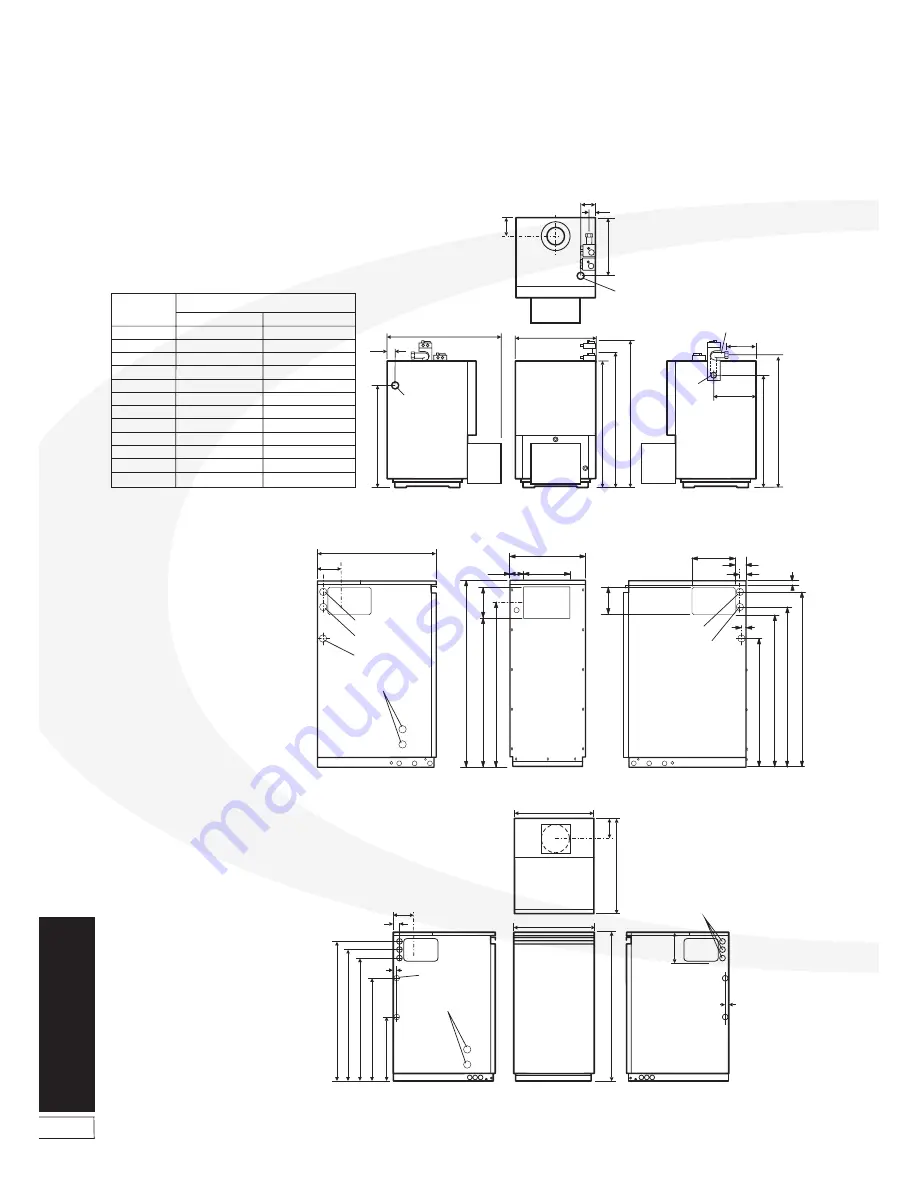
2.6 Boiler dimensions
Figure 2-2:
15/21 Kitchen/Utility dimensions
Figure 2-3:
15/26 Kitchen/Utility System dimensions
All dimensions in the diagrams above are in millimetres
Figure 2-1:
26/36, 36/46, 46/58, 58/70 Boiler House dimensions
FRONT VIEW
M
A
*M
B
LEFT SIDE
VIEW
Condensate
drain
C
D
G
Flow
*Flow
RIGHT SIDE
VIEW
E
*E
F
*F
The 26/36, 36/46 Dual thermostat is mounted on a bracket
and a separate flow pipe is used. See Section 5.4.
The 46/58, 58/70 Dual thermostat is fitted into the top of the
boiler and a side flow tapping is used.
Note:
PLAN VIEW
Return
H
J
*K
L
A
B
C
D
E
F
G
H
J
K
L
M
705
460
600
560
*782
*125
30
330
90
*30
115
870
1022
540
868
835
938
285
30
415
115
-
115
*1072
Boiler House model
26/36, 36/46
46/58, 58/70
Dimension


