~ 3 ~
~ 4 ~
INSTALLATION:
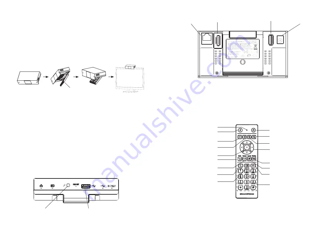
The GVC3212 can be installed on TV screen using its built-in bracket by fol
-
lowing the steps below :
1.
Open the rotating bracket under the main unit, as shown in the following
figure.
2.
Fasten the main unit to the top border of the TV.
3.
According to the thickness of the display device, adjust the rotating bracket
to the most suitable angle and ensure the top of the bracket sits properly.
Rotating Bracket
CONNECTING THE GVC3212:
1.
Connect the LAN port of the GVC3212 to the RJ-45 socket of a hub/switch
or a router (LAN side of the router) using the Ethernet cable.
2.
Connect the HDMI-out port of the GVC3212 to the HDMI port of the main
display device (e.g., TV) using the HDMI cable.
3.
Connect the 12V DC output plug to the power jack on the GVC. Then, plug
the power adapter into an electrical outlet.
4.
The display device (e.g., TV) will show the idle HOME screen with IP ad
-
dress on the top status bar.
5.
(Optional) Connect USB accessory (e.g., mouse, keyboard, USB flash
drive and etc) to the USB port.
6.
Use the Line-In port to connect a microphone (external audio input de
-
vice).
Note:
The total current limit of USB 1 and USB 2 is 800 mA.
USB Port
3.5mm LINE IN Port
Back View
1
3
2
4
LAN Port
HDMI-out Port
USB Port
DC-IN 12V
Bottom View
USING THE GVC3212 REMOTE CONTROL:
Power ON/OFF
Camera
Presentation
Zoom In
Navigation Keys:
Up/Down, Left/Right
Volume Up
OK
Layouts
Back
Mute
End Meeting
Zoom Out
Volume Down
Standard Keypad
Backspace
Send/Answer
LED Indicator
1.
Open the battery cover on the back of the remote control.
2.
Place two AAA batteries proprely and put the cover back on.
Note:
Users need to keep the two devices in front of each other without any
substantial obstruction in between.


