10
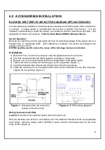
System Test Procedure (BVSO)
1) With the power re-established, block the chimney or vent pipe downstream of the switch.
2) Adjust the thermostat to call for heat.
3) Once the heating system has started the blocked vent switch should shut down the burner
within 10 minutes or sooner.
4) Once the system has cooled, the blocked vent switch can manually be reset.
5) This procedure should be tested a second time.
6) After testing the blocked vent switch the chimney should be cleared of obstruction and the
heating system should be tested over a long run cycle.
If the block vent switch shuts down the system, check to ensure there is enough draft in the
chimney and venting pipes.
AIR CONDITIONING
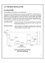
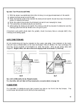
An air conditioning coil may be installed on the supply side only. Coils installed on the return
side will cause condensation on the heat exchanger; this will shorten the heat exchanger life
and may cause products of combustion to enter the house. Wire as per wiring label and
diagram. Height of the coil above the unit supply shall be at least 4” (102 mm).
KLR
KLF
See A/C coil Manufacturers Requirements.
To check the AC coil total air flow resistance, see procedure at page 34.
HUMIDIFIER
If a humidifier is installed ensure that no water can drip or run from it into the furnace. This
would cause deterioration and void the furnace warranty.
4 inch
minimum
4 inch
minimum
Summary of Contents for KLF-200
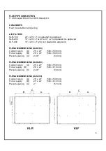
Page 7: ...6 KLR 200 DIMENSIONS Dimensions are in inches KLF 200 DIMENSIONS Dimensions are in inches...
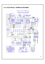
Page 25: ...24 8 0 ELECTRICAL WIRING DIAGRAMS...
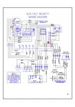
Page 26: ...25...
Page 27: ...26 GeniSys control schematic with the ST9103 Board...
Page 28: ...27 9 0 EXPLODED PARTS VIEW KLR 100 Exploded Parts View...
Page 30: ...29 KLR 200 Exploded Parts View...
Page 32: ...31 KLF 200 Exploded Parts View...


