Grafenthal PR-1000 User Manual Download Page 3


GRAFENTHAL GmbH  -  User Manual UPS 

PR-1000/-1500/-2000/-3000


- 2 - 


1. IMPORTANT SAFETY WARNING


Please  comply  with  all  warnings  and  operating  instructions  in  this  manual  strictly.  Save  this  manual 

properly and read carefully the following  instructions before installing the unit. Do not operate this 

unit before reading through all safety information and operating instructions carefully 
 

1-1. Transportation 


Please transport the UPS system only in the original package to protect against shock and 
impact. 


1-2. Preparation 


Condensation may occur if the UPS system is moved directly from cold to warm 
environment. The UPS system must be absolutely dry before being installed. Please allow at 
least two hours for the UPS system to acclimate the environment.  


Do not install the UPS system near water or in moist environments. 


Do not install the UPS system where it would be exposed to direct sunlight or near heater. 


Do not block ventilation holes in the UPS housing. 


1-3. Installation 


Do not connect appliances or devices which would overload the UPS system (e.g. laser 
printers) to the UPS output sockets.  


Place cables in such a way that no one can step on or trip over them.  


Do not connect domestic appliances such as hair dryers to UPS output sockets.  


The UPS can be operated by any individuals with no previous experience.  


Connect the UPS system only to an earthed shockproof outlet which must be easily 
accessible and close to the UPS system.  


Please use only VDE-tested, CE-marked mains cable (e.g. the mains cable of your 
computer) to connect the UPS system to the building wiring outlet (shockproof outlet).  


Please use only VDE-tested, CE-marked power cables to connect the loads to the UPS 
system.  


When installing the equipment, it should ensure that the sum of the leakage current of the 

UPS and the connected devices does not exceed 3.5mA. 


1-4. Operation 


Do not disconnect the mains cable on the UPS system or the building wiring outlet 
(shockproof socket outlet) during operations since this would cancel the protective earthing 
of the UPS system and of all connected loads.  


The UPS system features its own, internal current source (batteries). The UPS output 
sockets or output terminals block may be electrically live even if the UPS system is not 
connected to the building wiring outlet.  


In order to fully disconnect the UPS system, first press the OFF/Enter button to disconnect 
the mains.  


Prevent no fluids or other foreign objects from inside of the UPS system.  


Summary of Contents for PR-1000

Page 1: ...GRAFENTHAL USV PR 1000 PR 1500 PR 2000 PR 3000 Uninterruptible Power Supply System USER MANUAL EN ...

Page 2: ...Maintenance service and faults 3 2 Installation and setup 4 2 1 Rear panel view 4 2 2 Setup the UPS 5 3 Operations 7 3 1 Button operation 7 3 2 LCD Panel 7 3 3 Audible Alarm 9 3 4 LCD display wordings index 9 3 5 UPS Setting 9 3 6 Operating Mode Description 13 3 7 Faults Reference Code 14 3 8 Warning indicator 14 4 Troubleshooting 15 5 Storage and Maintenance 17 6 Specifications 18 ...

Page 3: ...no one can step on or trip over them Do not connect domestic appliances such as hair dryers to UPS output sockets The UPS can be operated by any individuals with no previous experience Connect the UPS system only to an earthed shockproof outlet which must be easily accessible and close to the UPS system Please use only VDE tested CE marked mains cable e g the mains cable of your computer to connec...

Page 4: ...erations Unauthorized persons must be kept well away from the batteries Caution risk of electric shock The battery circuit is not isolated from the input voltage Hazardous voltages may occur between the battery terminals and the ground Before touching please verify that no voltage is present Batteries may cause electric shock and have a high short circuit current Please take the precautionary meas...

Page 5: ...odel Type Model Type PR 1000 Standard PR 1000L Long run PR 1500 PR 1500L PR 2000 PR 2000L PR 3000 PR 3000L 2 1 Rear panel view PR 1000 L 1500 L PR 2000 L PR 3000 L 1 Programmable outlets connect to non critical loads 2 Output receptacles connect to mission critical loads 3 AC input 4 Input circuit breaker 5 Network Fax Modem surge protection 6 Emergency power off function connector EPO 7 USB commu...

Page 6: ...put or outputs please follow below steps for the wiring configuration a Remove the small cover of the terminal block b Suggest using AWG14 or 2 1mm2 power cords Suggest using WG12 10 or 3 3mm2 5 3mm2 power cords for NEMA type c Upon completion of the wiring configuration please check whether the wires are securely affixed d Put the small cover back to the rear panel Step 3 Communication connection...

Page 7: ...S monitoring software to fully configure UPS shutdown You may insert provided CD into CD ROM to install the monitoring software If not please follow steps below to download and install monitoring software from the internet 1 Go to the website http www grafenthal com service support download center 2 Click GRAFENTHAL USV Management icon and then choose your required OS to download the software 3 Fo...

Page 8: ...n off the UPS in battery mode UPS will be in standby mode under power normal or transfer to Bypass mode if the Bypass enable setting by pressing this button Confirm selection key Press this button to confirm selection in UPS setting mode Select Button Switch LCD message Press this button to change the LCD message for input voltage input frequency battery voltage output voltage and output frequency...

Page 9: ...ates the load level by 0 25 26 50 51 75 and 76 100 Indicates overload Indicates the load or the UPS output is short circuit Programmable outlets information Indicates that programmable management outlets are working Mode operation information Indicates the UPS connects to the mains Indicates the battery is working Indicates the bypass circuit is working Indicates the ECO mode is enabled Indicates ...

Page 10: ...D display wordings index Abbreviation Display content Meaning ENA Enable DIS Disable ESC Escape HLS High loss LLS Low loss BAT Battery CF Converter EP EPO FA Fan TP Temperature CH Charger 3 5 UPS Setting There are three parameters to set up the UPS Parameter 1 It s for program alternatives There are 9 programs to set up Refer to below table Parameter 2 and parameter 3 are the setting options or va...

Page 11: ...tput voltage is 127Vac 02 Frequency Converter enable disable Interface Setting Parameter 2 3 Enable or disable converter mode You may choose the following two options CF ENA converter mode enable CF DIS converter mode disable 03 Output frequency setting Interface Setting Parameter 2 3 Output frequency setting You may set the initial frequency on battery mode BAT 50 presents output frequency is 50H...

Page 12: ... Interface Setting Parameter 3 Enable or disable Bypass function You may choose the following two options ENA Bypass enable DIS Bypass disable 07 Bypass voltage range setting Interface Setting Parameter 2 3 Set the acceptable high voltage point and acceptable low voltage point for Bypass mode by pressing the Down key or Up key HLS Bypass high voltage point For 208 220 230 240 VAC models 230 264 se...

Page 13: ...Programmable outlets setting Interface Setting Parameter 3 Set up backup time limits for programmable outlets 0 999 setting the backup time limits in minutes from 0 999 for programmable outlets which connect to non critical devices on battery mode 00 Exit setting ...

Page 14: ...rgy saving Frequency Converter mode When input frequency is within 40 Hz to 70 Hz the UPS can be set at a constant output frequency 50 Hz or 60 Hz The UPS will still charge battery under this mode Battery mode When the input voltage is beyond the acceptable range or power failure and alarm is sounding every 4 second UPS will backup power from battery Bypass mode When input voltage is within accept...

Page 15: ...er soft start fail 11 x Over temperature 41 x Inverter voltage high 12 x Over load 43 3 8 Warning indicator Warning Icon flashing Alarm Low Battery Sounding every second Overload Sounding twice every second Battery is not connected Sounding every second Over Charge Sounding every second Site wiring fault Sounding every second EPO enable Sounding every second Fan Failure Sounding every second Over ...

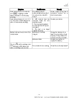
Page 16: ...battery is incorrectly connected Check if all batteries are connected well Fault code is shown as 27 and the icon is lighting on LCD display and alarm is continuously sounding Battery voltage is too high or the charger is fault Contact your dealer Fault code is shown as 28 and the icon is lighting on LCD display and alarm is continuously sounding Battery voltage is too low or the charger is fault ...

Page 17: ...ontinuously sounding A UPS internal fault has occurred There are two possible results 1 The load is still supplied but directly from AC power via bypass 2 The load is no longer supplied by power Contact your dealer Battery backup time is shorter than nominal value Batteries are not fully charged Charge the batteries for at least 5 hours and then check capacity If the problem still persists consult...

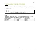
Page 18: ... case please contact your dealer Storage Before storing charge the UPS 5 hours Store the UPS covered and upright in a cool dry location During storage recharge the battery in accordance with the following table Storage Temperature Recharge Frequency Charging Duration 25 C 40 C Every 3 months 1 2 hours 40 C 45 C Every 2 months 1 2 hours Be sure to deliver the spent battery to a recycling facility o...

Page 19: ...e when the utility is normal 130 UPS shuts down immediately at battery mode or transfer to bypass mode when the utility is normal Current Crest Ratio 3 1 Harmonic Distortion 3 THD Linear Load 6 THD Non linear Load 4 THD Linear Load 7 THD Non linear Load Transfer Time AC Mode to Batt Mode Zero Inverter to Bypass 4 ms Typical Waveform Batt Mode Pure Sinewave Efficiency AC Mode 85 88 Battery Mode 83 ...

Reviews: