


•••••••••••••••••••••••••••••••••••••••••••••••••••••••••••••••••••••••••••••••••••••••••••••••••••••••••••••••••••••••••••••••••••••••••••••••••••••••••••••••••••••••••••••••••••••••••••••••••••••••••••••
Copyright © 2021 White Knight Fluid Handling | A Graco company
Version 1.0.1 | 3 December 2021 | Page 1
187 E. 670 S., Kamas, UT 84036
435.783.6040 888.796.2476
https://wkfluidhandling.com
Owner’s Manual
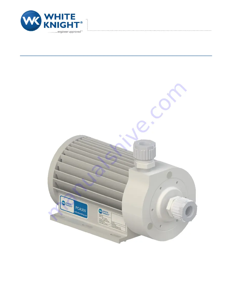
PCA300
140 LPM/37 GPM
4.75 BAR/69 PSI


