


Setup
24
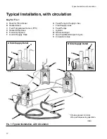
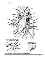
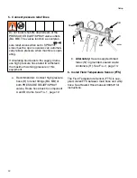
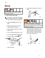
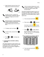
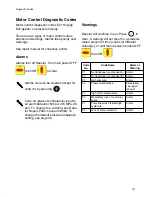
5. Connect pressure relief lines
a. Recommended: Connect high pressure
hose (R) to relief fittings (BA, BB) of
both PRESSURE RELIEF/SPRAY
valves, Route hose back to component
A and B drums. See F
IG
. 1, page 12.
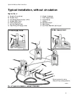
b.
Alternately:
Secure supplied bleed
tubes (N) in grounded, sealed waste
containers (H). See F
IG
. 2, page 13.
6. Install Fluid Temperature Sensor (FTS)
The Fluid Temperature Sensor (FTS) is sup-
plied. Install FTS between main hose and whip
hose. See Heated Hose manual 309572 for
instructions.
Do not install shutoffs downstream of the
PRESSURE RELIEF/SPRAY valve outlets
(BA, BB). The valves function as overpres-
sure relief valves when set to SPRAY
.
Lines must be open so valves can automati-
cally relieve pressure when machine is oper-
ating.
If circulating fluid back to the supply drums,
use high pressure hose rated to withstand
the maximum working pressure of this
equipment.
ti9880a
BA
BB
R
R
SB
SA


