background image

4

307013

Installation

Grounding

WARNING

FIRE AND EXPLOSION HAZARD
Before operating, ground the system as
explained below. Also read the section
FIRE AND EXPLOSION HAZARD on
page 3.

To reduce the risk of static sparking, ground the pump
and all other components used or located in the spray/
dispensing area. Check your local electrical code for
detailed instructions for your area and type of equip-
ment and be sure to ground all of these components.

D

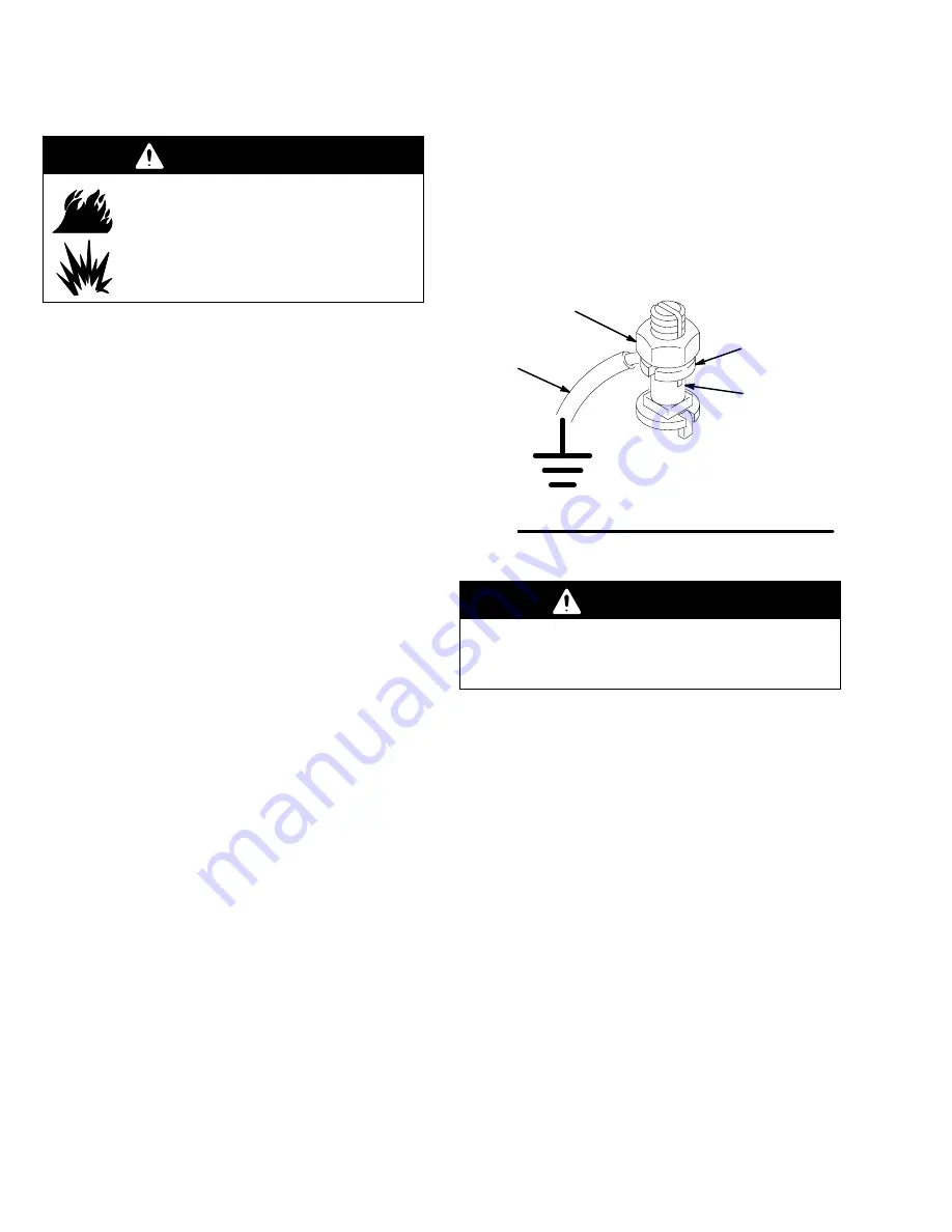
Pump:  loosen the grounding lug locknut (W) and
washer (X). Insert one end of a 12 ga (1.5 mm

2

)

minimum ground wire (Y) into the slot in lug (Z) and
tighten the locknut securely. See Fig. 1. Connect
the other end of the wire to a true earth ground.
Order Part No. 237569 Ground Wire and Clamp.

D

Air and Fluid Hoses:  Use only electrically conduc-
tive hoses with a maximum  of 500 feet (150 m)
combined hose length to ensure grounding continu-
ity.

D

Air Compressor:  follow the air compressor
manufacturer’s recommendations

D

Spray gun/dispensing valve: obtain grounding
through connection to a properly grounded fluid
hose and pump.

D

Fluid supply container: according to local code.

D

Object being sprayed:  according to local code.

D

All solvent pails used when flushing, according to
local code. Use only metal pails, which are conduc-
tive. Do not place the pail on a non-conductive
surface, such as paper or cardboard, which inter-
rupts grounding continuity.

D

To maintain grounding continuity when flushing or
relieving pressure, 
always hold a metal part of the
gun firmly to the side of a grounded metal pail, then
trigger the gun.

Fig. 1

W

X

Y

Z

0864

Flushing Safety

WARNING

To reduce the risk of serious injury whenever you
are instructed to relieve pressure, always follow the
Pressure Relief Procedure on page 7.

Before flushing, be sure the entire system and flushing
pails are properly grounded. Refer to Grounding  at
left. Follow the Pressure Relief Procedure on page
7, and remove the spray tip/nozzle from the gun/dis-
pensing valve. Always use the lowest possible fluid
pressure, and maintain firm metal-to-metal contact
between the gun/dispensing valve and the pail during
flushing to reduce the risk of fluid injection injury, static
sparking, and splashing.

Summary of Contents for Ratio King 224434

Page 1: ...m Air Input Pressure Model 224434 Series A Stubby Size with Standard Air Motor and Severe Duty Displacement Pump with leather packings Severe Duty Displacement Pumps have an abrasion and corrosion resistant displacement rod and sleeve Refer to the Technical Data in the separate displace ment pump manual 307728 for Wetted Parts informa tion GRACO INC P O BOX 1441 MINNEAPOLIS MN 55440 1441 ECOPYRIGH...

Page 2: ...d leaks with your hand body glove or rag D Do not blow back fluid this is not an air spray system D Always have the tip guard and the trigger guard on the spray gun dispensing valve when spraying dispensing D Be sure the gun trigger safety operates before spraying D Lock the gun valve trigger safety when you stop spraying D Follow the Pressure Relief Procedure on page 7 whenever you are instructed...

Page 3: ...injury D This equipment is for professional use only D Read all the instruction manuals tags and labels before operating the equipment D Use the equipment only for its intended purpose If you are uncertain about usage call your Graco distributor D Do not alter or modify this equipment Use only genuine Graco parts and accessories D Check the equipment daily Repair or replace worn or damaged parts i...

Page 4: ...unding through connection to a properly grounded fluid hose and pump D Fluid supply container according to local code D Object being sprayed according to local code D All solvent pails used when flushing according to local code Use only metal pails which are conduc tive Do not place the pail on a non conductive surface such as paper or cardboard which inter rupts grounding continuity D To maintain...

Page 5: ... Air Regulator Air Line Filter Bleed Type Master Air Valve for accessories Air Supply Hose Fluid Drain Valve required Fluid Supply Hose Spray Gun Fluid Suction Hose Exhaust Port for Muffler 1 1 4 npt 16 Exhaust Holes Wall Bracket Packing Nut Wet Cup Ground Wire required Typical Installation J A B C D E F G H K L M N Y P PLUG WHEN EXHAUSTING THROUGH MUFFLER R S ...

Page 6: ...uid hose H to the pump s 1 npt f fluid outlet using a suitable adapter Connect a fluid suction hose and tube M to the pump s 1 1 2 npt f fluid intake Use an electrically conductive 3 4 in ID minimum air hose H to supply air to the pump Air Line Accessories Install the following accessories in the order shown in the Typical Installation using adapters as necessary D An air line lubricator C provide...

Page 7: ...air to the pump 3 Close the bleed type master air valve required in your system 4 Unlock the trigger safety 5 Hold a metal part of the gun valve firmly to the side of a grounded metal pail and trigger the gun valve to relieve pressure 6 Lock the trigger safety 7 Open the drain valve required in your system having a container ready to catch the drainage 8 Leave the drain valve open until you are re...

Page 8: ...he spray gun is opened and closed In a circulating system the pump will run continuously and will speed up or slow down as supply demands until the air supply is shut off Use an adequately sized air regulator E to control the pump speed and the fluid pressure Always use the lowest air pressure necessary to get the desired results Higher pressures waste fluid and cause pre mature wear of the pump p...

Page 9: ...om pump and fluid lines Air in displacement pump and hose Reprime Check valves need adjustment Adjust see manual 307728 Packing nut too tight or too loose Adjust see manual 307728 Worn throat packings Replace see manual 307728 Pump operates but output low on down stroke Held open or worn intake valve Clear service see manual 307728 Pump operates but output low on up stroke Held open or worn fluid ...

Page 10: ...ns 5 Refer to instruction manual 306968 supplied for air motor service instructions Reconnecting the Displacement Pump 1 Orient the pump s fluid outlet A to the air motor s air inlet B as was noted in step 2 under Discon necting the Displacement Pump Position the displacement pump 2 on the tie rods 31 2 Place the coupling nut 32 on the connecting rod T Insert the couplers 33 into the coupling nut ...

Page 11: ...11 307013 Service 03293 Fig 2 1 2 28 31 26 A B S T 1 2 Torque to 40 50 ft lb 54 68 NSm Torque to 145 155 ft lb 195 210 NSm 1 2 1 Model 224434 shown 32 33 ...

Page 12: ... Includes items 1 33 Ref No Part No Description Qty 1 207647 AIR MOTOR See Manual 306968 for parts 1 2 224435 DISPLACEMENT PUMP ASSY See Manual 307728 for parts 1 26 101712 NUT lock 5 8 11 3 28 102176 WRENCH 1 31 167911 ROD tie 7 178 mm shoulder to shoulder 3 32 186925 NUT coupling 1 33 184129 COUPLING 1 03293 1 2 28 31 26 32 33 ...

Page 13: ...13 307013 Notes ...

Page 14: ...1079 5 mm 533 4 mm 3 4 npt f AIR INLET 1 npt f FLUID OUTLET 1 1 2 npt f FLUID INTAKE See 306968 for Air Motor Dimensional Drawing WEIGHT 110 lb 50 kg 1 875 48 mm FOR OUTLET RISER TUBE 3 712 94 mm 3 464 88 mm 4 0 102 mm 3 712 94 mm 4 0 102 mm 5 8 11 UNC 3 FOR PUMP ATTACHMENT 0 44 11 1 mm DIA 4 01838 ...

Page 15: ... and operating air pressure psi MPa bar 1 Locate desired flow along bottom of chart 2 Follow vertical line up to intersection with selected fluid outlet pressure curve black Follow left to scale to read fluid outlet pressure To find Pump Air Consumption m min or scfm at a specific fluid flow lpm gpm and air pressure psi MPa bar 1 Locate desired flow along bottom of chart 2 Read vertical line up to...

Page 16: ...h of warranty shall be as set forth above The buyer agrees that no other remedy including but not limited to incidental or consequential damages for lost profits lost sales injury to person or property or any other incidental or consequential loss shall be available Any action for breach of warranty must be brought within two 2 years of the date of sale Graco makes no warranty and disclaims all im...

Reviews: