background image

Notes 

34

3A0248C

Notes

Summary of Contents for Project Painter Plus 257025

Page 1: ...e materials having flash points lower than 70 F 21 C This includes but is not limited to acetone xylene toluene or naptha For more information about your material request MSDS from distributor or retailer Visit our website http magnumbygraco com EN Project Painter Plus Model 257025 ti14951a IMPORTANT SAFETY INSTRUCTIONS Read all warnings and instructions in this manual and on the sprayer cord Save...

Page 2: ...cord or plug is required do not connect the grounding wire to either flat blade terminal The wire with insulation having an outer surface that is green with or without yellow stripes is the grounding wire Check with a qualified electrician or serviceman when the grounding instructions are not completely understood or when in doubt as to whether the product is properly grounded Do not modify the pl...

Page 3: ... sprayed Read all Material Safety Data Sheets MSDS and container labels provided with the paints and solvents Follow the paint and solvents manufacturer s safety instructions Fire extinguisher equipment shall be present and working Sprayer generates sparks When flammable liquid is used in or near the sprayer or for flushing or cleaning keep sprayer at least 20 feet 6 m away from explosive vapors S...

Page 4: ...ydrocarbon solvents or fluids containing such solvents in pressurized aluminum equipment Such use can cause serious chemical reaction and equipment rupture and result in death serious injury and property damage MOVING PARTS HAZARD Moving parts can pinch or amputate fingers and other body parts Keep clear of moving parts Do not operate equipment with protective guards or covers removed Pressurized ...

Page 5: ...ge suction tube and place into waste pail 4 If spraying oil based materials sub merge suction tube in paint thinner or compatible oil based cleaning solution If spraying water based materials sub merge suction tube in water 5 Turn Power switch ON With Spray Prime valve still at PRIME turn Pressure Con trol Knob to right clockwise until pump starts 6 Allow fluid to flow out of prime tube into waste...

Page 6: ...f tip clog occurs this spray tip reverses enabling you to quickly clear obstructions without disassem bly 4 Turn Pressure Control Knob right clock wise to increase pressure at the gun and turn it left counterclockwise to decrease the pressure 5 Point Gun at surface to be sprayed about 12 in 304 mm away from surface and begin moving the gun before you trigger it A good spray pattern is evenly distr...

Page 7: ...e and inlet screen 4 Unscrew inlet screen from suction tube Thread power flush attachment onto suction tube 5 Trigger gun into paint pail and lower spray prime valve to SPRAY Turn power switch ON to push paint in hose into paint pail When water comes out of the gun keep gun triggered and move aim of gun into waste pail 6 Trigger gun into waste pail for 1 2 minutes until relatively clear water come...

Page 8: ...un guard tip and filter 10 Submerge suction tube and drain tube in storage fluid Always use Graco pump armor or mineral spirits paint thinner for storage fluid Lift spray prime valve to PRIME Turn power switch ON 11 Turn pressure control knob to right clockwise until pump starts 12 When storage fluid comes out of drain tube turn power switch OFF 13 Lower prime spray valve to SPRAY 14 Install inlet...

Page 9: ...f you intend to use this equipment in this type of application you must comply with NFPA 33 and OSHA requirements for the use of flammable and combustible materials Model Name Series Dispense Rate gpm lpm Hose Length and Diameter Maximum Hose Length Gun Model Maximum Working Pressure PSI MPa bar Project Painter Plus A 0 24 gpm 0 91 lpm 1 4 in x 25 ft 6 4 mm x 7 5 m 50 ft 15 m SG2 2800 19 193 ...

Page 10: ...olvent pails used when flushing follow local code Use only conductive metal pails placed on a grounded surface such as concrete Do not place the pail on a nonconductive surface such as paper or cardboard which interrupts grounding continuity Grounding the metal pail connect a ground wire to the pail by clamping one end to pail and other end to ground such as a water pipe Maintaining grounding cont...

Page 11: ...Notes 3A0248C 11 Notes ...

Page 12: ...ion directs pressurized fluid to paint hose Automatically relieves system pressure in overpressure situations L Inlet screen Prevents debris from entering pump M Paint hose Transports high pressure fluid from pump to spray gun N Handle Used to help transport sprayer Q Tip guard Reduces risk of fluid injection injury R Reversible spray tip Atomizes fluid being sprayed forms spray pattern and contro...

Page 13: ...Component Identification Project Painter Plus 3A0248C 13 Project Painter Plus ti14952a C1 M V R Q L G D H J B N C S A T U X W ...

Page 14: ...e pressure 4 Engage trigger lock If you suspect the spray tip or hose is clogged or that pressure has not been fully relieved after following the steps above VERY SLOWLY loosen tip guard retaining nut or hose end coupling to relieve pressure gradually then loosen completely Clear hose or tip obstruction Read Unclogging Spray Tip page 18 ti8908a Trigger Locked Trigger Unlocked ti8909a ti2810a NOTE ...

Page 15: ...to gun Use two wrenches to tighten securely 3 Connect other end of hose to sprayer 4 Turn OFF power switch 5 Turn Pressure Control Knob all the way left coun ter clockwise to minimum pressure ti12960a ti9681a ti14955a NOTE If hose is already connected make sure connections are tight ti2810a ti12940a ...

Page 16: ...power switch OFF NOTE These units are not intended for lacquers When spraying water based materials flush the system thoroughly with water When spraying oil based materials flush the system thoroughly with mineral spirits or compatible oil based flushing solvent To spray water based materials after spraying oil based materials flush the system thoroughly with water first The water flowing out of p...

Page 17: ...Transfer prime tube to paint pail and clip prime tube to suction tube Install Tip and Guard on Gun 1 Engage trigger lock 2 Verify tip and guard parts are assembled in order shown 3 Screw tip and guard assembly on gun Tighten retaining nut ti14963a PAINT ti5580a ti8909a ti13960a ti8908a Motor stopping indicates pump and hose are primed with paint If motor continues to run the sprayer is not properl...

Page 18: ...ions are provided in Get ting Started with Basic Spraying Techniques section of this manual page 20 Unclogging Spray Tip To avoid fluid splashback Never pull gun trigger when arrow shaped handle is between SPRAY and UNCLOG positions Tip must be pushed all the way into guard 1 To unclog tip obstruction engage trigger lock 2 Point arrow shaped handle backward to unclog position 3 Aim gun at piece of...

Page 19: ... paint that comes out of the gun HINTS Use larger tip hole sizes with thicker coatings and smaller tip hole sizes with thinner coatings Tips wear with use and need periodic replacement Fan Width Fan width is the size of the spray pattern which deter mines the area covered with each stroke Narrower fans deliver a thicker coat and wider fans deliver a thinner coat HINTS Select a fan width best suite...

Page 20: ...rect spray angle causes an uneven finish Flex wrist to keep gun pointed straight Fanning gun to direct spray at angle causes uneven finish Triggering Gun Pull trigger after starting stroke Release trigger before end of stroke Gun must be moving when trigger is pulled and released Aiming Gun Aim tip of gun at bottom edge of previous stroke over lapping each stroke by half 12 in 30 cm even finish th...

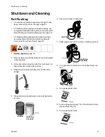
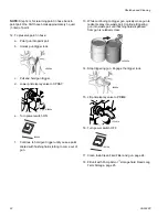
Page 21: ... Turn pressure control knob to the Prime Clean set ting 9 Turn power switch ON 10 Flush until approximately 1 3 of the flushing fluid is emptied from the pail 11 Turn power switch OFF For short term shutdown periods overnight to two days refer to Short Term Storage page 25 For flushing after spraying oil based coatings use compatible oil based flushing fluid or mineral spirits Read Priming and Flu...

Page 22: ...l Continue triggering gun into waste pail until flushing fluid dispensed from gun is relatively clear 14 Stop triggering gun Engage the trigger lock 15 Lift prime spray valve to PRIME 16 Turn power switch OFF 17 Clean InstaClean Fluid Filter and gun page 24 18 Fill unit with Pump Armor storage fluid Read Long Term Storage page 25 o preserve paint in hose trigger gun into paint pail to expel the re...

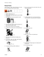
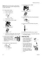
Page 23: ...re Control knob to the Prime Clean set ting 7 Screw power flush attachment to garden hose Close valve 8 Turn on water Open valve Rinse paint off suction tube prime tube and inlet screen 9 Turn lever to close power flush attachment 10 Unscrew inlet screen from suction tube Place inlet screen in waste pail 11 Connect garden hose to suction tube with Power Flush attachment Leave prime tube in waste p...

Page 24: ...den hose Close Power Flush attach ment 22 Unscrew Power Flush attachment from suction tube 23 Clean InstaClean fluid filter and gun page 24 24 Fill unit with Pump Armor storage fluid Read Long Term Storage page 25 Cleaning Gun Clean gun fluid filter d with water or flushing solvent and a brush every time you flush the system Replace gun filter if damaged Remove tip and guard and clean with water o...

Page 25: ...used to loosen and remove dried on material if needed d Wipe paint off outside of gun using a soft cloth moistened with water or flushing solvent Long Term Storage more than 2 days 1 Place suction tube in Pump Armor storage fluid bot tle and prime tube in waste pail 2 Lift prime spray valve to PRIME 3 Turn power switch ON ti14964a ti14965a ti8908a ti9671a Always circulate Pump Armor storage fluid ...

Page 26: ...rayer 1 Screw inlet screen onto suction tube 2 Coil hose Leave it con nected to sprayer Wrap hose around hose wrap bracket 3 Secure a plastic bag around suction tube to catch any drips 4 Store sprayer indoors NOTICE To prevent damage to the equipment make sure all water is drained out of sprayer and hoses before storing Do not allow water to freeze in sprayer or hose Do not store sprayer under pre...

Page 27: ...hes to tighten Tips Always clean tips with compatible solvent and brush after spraying Tips may require replacement after 15 gallons 57 liters or they may last through 60 gallons 227 liters depending on abrasiveness of paint Do not spray with worn tip The Project Painter Plus is a non repairable sprayer Please refer to the Part List page 32 for a list of replaceable parts NOTICE Protect the intern...

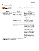
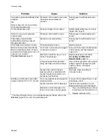
Page 28: ...Replace extension cord Read Grounding and Electric Require ments page 10 Sprayer electric cord is damaged Check for broken insulation or wires Replace electric cord if damaged Paint and or water is frozen or hard ened in pump Unplug sprayer from outlet If frozen do NOT try to start sprayer until it is completely thawed or you may dam age the motor control board and or drivetrain Make sure power sw...

Page 29: ... does not build up pressure Pump is not primed Prime pump Inlet screen is clogged Clean debris off inlet screen and make sure suction tube is immersed in fluid Suction tube is not immersed in paint Make sure suction tube is immersed in paint Paint pail is empty Refill hopper or paint pail Reprime sprayer Suction tube is leaking Inlet tube fitting improperly or not securely attached Prime Spray Val...

Page 30: ...lves may be worn Take sprayer to authorized service center Material too thick Thin material Hose too long if extra section is added Remove section of hose Spray gun stopped spraying Pump was not primed with flushing fluid Remove suction tube from paint Prime pump with water or flushing solvent based flushing fluid Suction tube is leaking Tighten suction tube connection Inspect for cracks or vacuum...

Page 31: ...ent holes clear of obstructions and overspray and keep sprayer open to air Extension cord is too long or not a heavy enough gauge Replace extension cord Read Grounding and Electrical Requirements page 10 Unregulated electrical generator being used has excessive voltage Use electrical generator with a proper voltage regulator Sprayer requires 120VAC 60 Hz 1500 Watt generator Sprayer was operated at...

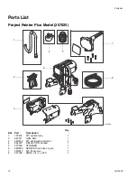
Page 32: ...14968a 1 2 3 4 5 6 7 8 Ref Part Description Qty 1 197607 KIT suction tube 1 2 243011 GUN SG2 1 3 24D616 KIT enclosure and stand 1 4 244035 DEFLECTOR barbed 1 5 257002 STRAINER 1 6 24D626 SPRAYER no hose or gun 1 7 24D617 KIT front cover 1 8 247339 HOSE 1 4 in x 25 ft 1 ...

Page 33: ...PSM external thread Inlet screen on suction tube 35 mesh 450 micron Wetted parts pump hose stainless steel brass leather ultra high molecular weight polyethylene UHMWPE carbide nylon aluminum PVC polypropylene fluroelastomer Wetted parts gun aluminum brass carbide nylon plated steel stainless steel UHMWPE zinc Generator requirement 1500 Watt minimum Electrical power requirement 120 Vac 60 Hz 15A 1...

Page 34: ...Notes 34 3A0248C Notes ...

Page 35: ...Notes 3A0248C 35 Notes ...

Page 36: ...including but not limited to incidental or consequential damages for lost profits lost sales injury to person or property or any other incidental or consequential loss shall be available Any action for breach of warranty must be brought within two 2 years of the date of sale GRACO MAKES NO WARRANTY AND DISCLAIMS ALL IMPLIED WARRANTIES OF MERCHANTABILITY AND FITNESS FOR A PARTICULAR PURPOSE IN CONN...

Page 37: ...Standard Warranty 3A0248C 37 www graco com Revised February 2013 ...

Reviews: