


307962 11
Air Motor Service
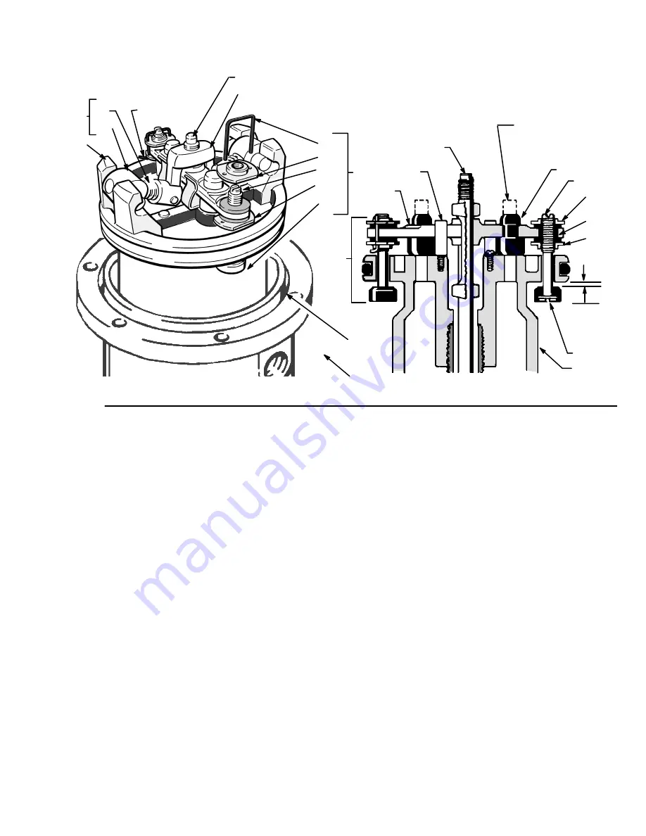
Fig 4
101
107
D
118
B
114A
113
116c
102
110
109
C
116a
120
113
114A
111
114B
112
116
CUT OFF TOPS OF
POPPETS AS
INDICATED BY
DOTTED LINES
101
119
0.145”
(3.68 mm)
CUTAWAY VIEW
114B
C
PUSH TOGGLES (B) IN
AND THEN UP
112
TURN WIRES UP
NOTE:
Refer to Fig. 4 for Steps 5 to 21.
5.
Use a screwdriver to push down on the yoke (107)
and snap the toggle assemblies (B) down.
6.
Remove the lockwires (118) and upper adjusting
nuts (114A) from the air transfer valves (C).
7.
Screw the stems (113) out of the grommets (111) and
lower adjusting nuts (114B).
8.
Remove the poppets (112) and inspect them for
cracks.
9.
Grip the rocker (109) with pliers, compress the spring
(110), swing the toggle assembly (B) up and away
from the piston lugs (D). Remove the parts.
10. Inspect the actuator (119) to be sure it is supported
by the spring clips (116a), but slides into them easily.
11. Remove the yoke (107), actuator (119) and the trip
rod (101).
12. Remove the poppets (120): stretch them out and cut
them with a sharp knife.
13. Pull the piston (116) out of the base (102). Remove
the o–ring (124) in the base casting.
14. Clean all parts thoroughly and inspect for wear or
damage. Inspect the polished surfaces of the piston,
piston rod and cylinder walls for scratches or wear.
Replace parts as necessary. Lubricate all parts with
a light waterproof grease.
15. Install the o-ring (124) in the groove inside the base
(102). Install the o-ring (123) around the rim of the
base. Install the o-ring (121) around the piston
(116c). Slide the piston rod down into the base (102).
16. Pull the poppets (120) into the actuator (119) and clip
off the top part of the poppets as shown with dotted
lines. See the
Cutaway View
.
17. Install the poppets (112) on the stems (113). Reas-
semble the stems (113), grommets (111), adjusting
nuts (114A,114B). Install the wires (118). Turn the
ends of the wires up to hold them in place.
18. Install the trip rod (101), actuator (119), yoke (107)
and the toggle assemblies (B) on the piston (116).
19. Adjust the stems (113) so there is a 0.145 in. (3.68
mm) clearance between the poppets (112) and the
piston (116) when the toggle assemblies are in the
down position. See the
Cutaway View
. Special
gauge, Part No. 171818, is available.
20. Snap the toggle assemblies (B) to the up position.
Reinstall the cylinder (115) and hold the trip rod (101)
in place with tool 207579. Apply a medium strength
thread locking compound to the threads of the trip
rod (101). Torque cap nut (131) to the trip rod (101).
21. Reassemble the air motor to the displacement pump.
Before mounting the pump, connect an air hose to
the air motor and run the pump to be sure it operates
smoothly.


