background image

Installation 

10

309967A

Models 246915, 246916, 253388 and 253389

(F

IG

. 6)

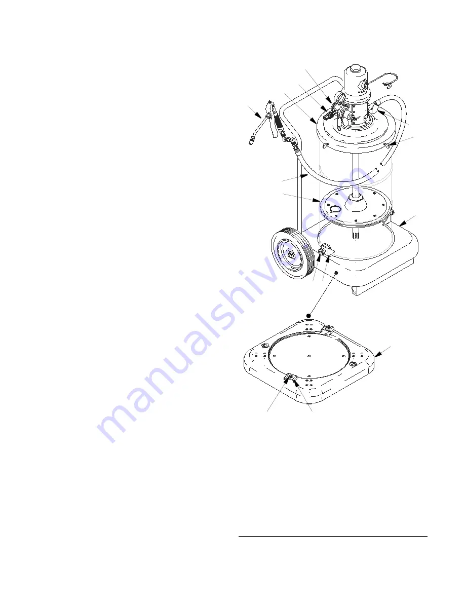
1.

For Models 246915 and 253388: Assemble the por-
table base (8) as shown in the parts drawing on 
page 17

For Models 246916 and 253389: Assemble the 
truck (7) as shown in the parts drawing on page 17.

2.

Remove the fluid outlet adapter included with the 
pump, and screw the holster (6) into the pump out-
let, using thread sealant.

3.

Place an open 120–lb drum of grease on the mount-
ing base or truck, and secure it with hold-down 
clamps (7d or 8d).

For Models 246915 and 253388: Use pointed end of 
clamps (8d) for steel drums only. Position the clamp 
above the drum bead. Tighten bolts (8b). Reverse 
clamps (8d) to use the flat end for fiber drums.

For Models 246916 and 253389: Use pointed end of 
clamps (7d) for steel drums only. Position the clamp 
above the drum bead. Tighten the thumbnuts (7c).

4.

Press the follow plate (5) down firmly onto the 
grease, and rotate it to eliminate air pockets and 
reduce channeling.  Insert the pump through the 
cover (4).  Slide the cover up far enough to let the 
pump pass easily through the follow plate grommet.

5.

Secure the cover on the drum with the thumbscrews 
(A).  It is not necessary to bolt the pump to the 
cover.

6.

Assemble the gun (2b) and hose (2a), and connect 
the hose to the pump fluid outlet.

7.

Connect the nipple (2d) to the pump air inlet or air 
regulator (9b) inlet, whichever is applicable.  Con-
nect the quick–disconnect coupler (2c) to the air 
supply hose.

F

IG

. 6

Model 253389 shown

246916

4

5

8d

7d

7c

A

2b

2a

6

7

06790

8b

2c, 2d

9b

8

Summary of Contents for Mini Fire-Ball 225 246910

Page 1: ...avy grease See page 2 for model numbers 5000 psi 34 MPa 345 bar Maximum Working Pressure 100 psi 0 7 MPa 7 bar Maximum Air Working Pressure Contents Models 2 Warnings 3 Operation Service 4 Installation 5 Operation 11 Parts 12 Sound Data 18 Graco Standard Warranty 20 Graco Information 20 Important Safety Instructions Read all warnings and instructions in this manual Save these instructions 253388 M...

Page 2: ...0653 246911 35 50 lb 16 23 kg 204574 253385 35 50 lb 16 23 kg 204574 246913 35 50 lb 16 23 kg 2 wheel truck 204574 253386 35 50 lb 16 23 kg 2 wheel truck 204574 246914 120 lb 55 kg 204574 220654 253387 120 lb 55 kg 204574 220654 246915 120 lb 55 kg portable 204574 220654 253388 120 lb 55 kg portable 204574 220654 246916 120 lb 55 kg 2 wheel truck 204574 220654 253389 120 lb 55 kg 2 wheel truck 204...

Page 3: ...acement parts only Do not alter or modify equipment Use equipment only for its intended purpose Call your Graco distributor for information Route hoses and cables away from traffic areas sharp edges moving parts and hot surfaces Do not kink or over bend hoses or use hoses to pull equipment Keep children and animals away from work area Comply with all applicable safety regulations SKIN INJECTION HA...

Page 4: ...static sparking or you feel a shock stop operation immediately Do not use equipment until you identify and correct the problem Keep a working fire extinguisher in the work area TOXIC FLUID OR FUMES HAZARD Toxic fluids or fumes can cause serious injury or death if splashed in the eyes or on skin inhaled or swallowed Read MSDS s to know the specific hazards of the fluids you are using Store hazardou...

Page 5: ...urely Connect the other end of the ground wire to a true earth ground See FIG 1 To order a ground wire and clamp order Part No 222011 Air and fluid hoses use only grounded hoses Air compressor follow manufacturer s recommenda tions Dispense valve ground through connection to a prop erly grounded fluid hose and pump Fluid supply container follow local code To maintain grounding continuity when flus...

Page 6: ...essed air supply For models 253384 through 253390 install the pro vided air regulator safety valve K at the pump air inlet with the nipple 9a also included Key A Fluid dispense line B Pump ground wire required C Air regulator D Main air supply line E Air filter F Pump lubricator G Pump runaway valve H Bleed type master air valve required J Quick disconnect couple and nipple K Air regulator 9b with...

Page 7: ...eling 3 Insert the pump through the cover 4a and slide the cover up far enough to let the pump pass easily through the follow plate grommet The pump stop plate 4b will secure the pump in place 4 Place the cover 4a on the pail and tighten the thumbscrews 4f 5 Assemble the gun 2b and hose 2a and connect the hose to the pump fluid outlet 6 Connect the nipple 2d to the pump air inlet or air regulator ...

Page 8: ... 7c 3 Remove the cover from the pail of lubricant Place the pail of lubricant into the truck pail 4 Secure the cover 4 on the pail with the three thumbscrews A 5 Insert the pump riser tube through the top of the cover 4 Lower the pump until it rests on the cover 6 Assemble the gun 2b and hose 2a and connect the hose to the pump fluid outlet 7 Connect the nipple 2d to the pump air inlet or air regu...

Page 9: ...cant surface to eliminate air pockets and prevent channeling 3 Place the cover 4 on the pail ant tighten the thumbscrews A 4 Connect the swivel adapter to the pump fluid outlet Connect fluid hose 3c to the swivel adapter Con nect a suitable dispense valve 5 Connect the swivel adapter to the pump air inlet or air regulator 9b whichever is applicable Connect the air hose 3a to the swivel Connect the...

Page 10: ...ps 8d to use the flat end for fiber drums For Models 246916 and 253389 Use pointed end of clamps 7d for steel drums only Position the clamp above the drum bead Tighten the thumbnuts 7c 4 Press the follow plate 5 down firmly onto the grease and rotate it to eliminate air pockets and reduce channeling Insert the pump through the cover 4 Slide the cover up far enough to let the pump pass easily throu...

Page 11: ...re Relief Procedure When the pump is primed and with sufficient air supplied the pump starts when the dispensing valve is opened and shuts off when it is closed A pump runaway valve can be installed on the air line to automatically shut off the pump if it starts to run too fast Never allow the pump to run dry of the fluid being pumped A dry pump will quickly accelerate to a high speed possibly dam...

Page 12: ...168102 PLATE stop pump 4c 158048 BUMPER button rubber 1 4d 159608 RIVET 1 4e 150868 HOLDER gun 1 4f 100220 SCREW thumb 3 4g 100025 NUT 1 4 npsm thd 1 4h 100579 PIN cotter 1 8 x 1 1 5 220653 FOLLOW PLATE See manual 306345 for parts 1 9 240979 CE Kit for 253384 See parts on page 17 1 01517 1 4d 2 9 4a 4b 4e 4h 4g 5 4f 4c Ref No Part No Description Qty 1 246909 PUMP Mini Fire Ball 225 50 1 See manual...

Page 13: ...6 203976 HOLSTER 1 7 203650 TRUCK 2 wheel See parts list on page 17 1 9 240979 CE Kit for 253386 See parts on page 17 1 10 204134 PAIL 1 10 1 6 2 Model 253386 shown 01514 4 9 7 Ref No Part No Description Qty 1 246780 PUMP Mini Fire Ball 225 50 1 See manual 309966 for parts 1 3 222072 Hose and Fitting Kit 6 ft 1 8 m hose See parts list on page 16 1 4 204574 COVER See manual 306345 for parts 1 5 220...

Page 14: ...203976 HOLSTER 1 8 203622 PORTABLE BASE See parts list on page 17 1 9 240979 CE Kit for 235388 See parts on page 17 1 2 4 1 9 5 Model 253388 shown 253388 8 6 Ref No Part No Description Qty 1 246780 PUMP Mini Fire Ball 225 50 1 See manual 309966 for parts 1 2 236058 DISPENSE KIT 12 ft 3 7 m hose See parts list on page 16 1 4 204574 COVER See manual 306345 for parts 1 5 220654 FOLLOW PLATE See manua...

Page 15: ... Mini Fire Ball 225 50 1 See manual 309966 for parts 1 3 222072 Hose and Fitting Kit 6 ft 1 8 m hose See parts list on page 16 1 4 200326 COVER See manual 306345 for parts 1 5 223845 FOLLOW PLATE See manual 306345 for parts 1 9 240979 CE Kit for 253389 See parts on page 17 1 5 1 4 Model 253390 shown 8726 9 3 3 ...

Page 16: ...e manual 309032 1 2c 114558 COUPLER quick disconnect 1 2d 169971 NIPPLE quick disconnect 1 2e 202577 Z SWIVEL 1 2c 236058 2a 2d 2b 2e Ref No Part No Description Qty 3a 203320 HOSE air buna N 3 8 npt mbe x 6 ft 1 8 m 1 3b 155494 UNION 90 3 8 npt m x 3 8 npsm f swivel 1 3c 109150 HOSE fluid buna N 1 4 npt mbe x 6 ft 1 8 m 1 3d 155541 UNION 90 1 4 npt m x 1 4 npsm f swivel 1 3d 3c 3b 3a 222072 ...

Page 17: ...Ref No Part No Description Qty 8a 191750 BASE drum 1 8b 102547 BOLT hex head 5 16 18 x 1 5 2 8c 100214 WASHER lock 2 8d 191747 BRACKET 2 8e 100132 WASHER flat 2 8f 113660 RIVET 16 8g 113646 CASTER polyurethane 4 8b 8c 8e 8d 8a 8f 8g 203622 Attention To comply with CE directives the CE iden tification label must be affixed to the back of the cart or to the top of the drum cover Permanently mark the...

Page 18: ...s maximum air consumption maximum delivery and so on Sound data for the air motors of the pumps on these portable units is as follows Tested at 140 psi 1 0 MPa 10 bar at 100 cycles per minute Sound Pressure Level measured at 1 meter from unit 77 8 dB A Sound Power Level tested in accordance with ISO 9614 2 85 6 dB A ...

Page 19: ...309967A 19 ...

Page 20: ...orkmanship repairs will be made at a reasonable charge which charges may include the costs of parts labor and transportation THIS WARRANTY IS EXCLUSIVE AND IS IN LIEU OF ANY OTHER WARRANTIES EXPRESS OR IMPLIED INCLUDING BUT NOT LIMITED TO WARRANTY OF MERCHANTABILITY OR WARRANTY OF FITNESS FOR A PARTICULAR PURPOSE Graco s sole obligation and buyer s sole remedy for any breach of warranty shall be a...

Reviews: