background image

Repair

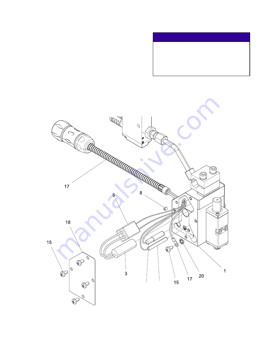
12. Reinstall the ground lead onto the manifold (1).

Note

Ensure the star washer (20) is placed

below the ground ring terminal.

13. Insert the RTD and thermal cutoff into the

manifold.

Note

Do not apply grease on the RTD.

14. Insert the terminal block (5) and heater cartridges

(3) in the manifold (1).

NOTICE

Do not pinch any wires when inserting the

terminal block in the manifold to prevent

removing wire insulation or disconnecting

wires. If wire insulation is removed, the RTD

or heaters could short out and need to be

replaced.

15. Reinstall the manifold cover plate (189).
16. Reconnect the cordset (17) to the heated hose.
17. Reconnect the solenoid valve power plug

housing to the solenoid valve.

R

T

Figure 14 Repair Parts

3A2805B

19

Summary of Contents for InvisiPac GS35 Plug-Free

Page 1: ...ved for use in explosive atmospheres or hazardous locations Important Safety Instructions Read all warnings and instructions in this manual Save these instructions 1500 psi 10 3 MPa 103 bar Maximum Working Fluid Pressure 80 psi 0 5 MPa 5 5 bar Maximum Air Pressure See page 6 for models and approval information PROVEN QUALITY LEADING TECHNOLOGY ...

Page 2: ...ssure Relief Procedure 11 Maintenance 12 Replace Inlet Filter 12 Troubleshooting 13 Check Module 15 Check Nozzle and Module 15 Check Heater 16 Check RTD 16 Repair 17 Before Beginning Repair 17 Replace Heater Cartridge 18 Replace RTD 18 Replace Thermal Cutoff 18 Replace Cordset 18 Replace Solenoid Valve 20 Replace Module 20 Replace Applicator 20 Notes 21 Parts 22 Kits and Accessories 30 Dimensions ...

Page 3: ...se electric shock Turn off and disconnect power at main switch before disconnecting any cables and before servicing equipment Connect only to grounded power source All electrical wiring must be done by a qualified electrician and comply with all local codes and regulations SKIN INJECTION HAZARD High pressure fluid from dispensing device hose leaks or ruptured components will pierce skin This may loo...

Page 4: ...th equipment wetted parts See Technical Data in all equipment manuals Read fluid and solvent manufacturer s warnings For complete information about your material request MSDS from distributor or retailer Do not leave the work area while equipment is energized or under pressure Turn off all equipment and follow the Pressure Relief Procedure when equipment is not in use Check equipment daily Repair o...

Page 5: ...a to help prevent serious injury including eye injury hearing loss inhalation of toxic fumes and burns This protective equipment includes but is not limited to Protective eyewear and hearing protection Respirators protective clothing and gloves as recommended by the fluid and solvent manufacturer 3A2805B 5 ...

Page 6: ... VDC 24P302 Nickel 120 Ohm 110 VAC 24P308 Nickel 120 Ohm N A Quad Part Module Spacing in mm RTD Type Solenoid Valve 24P077 0 88 22 4 Platinum 100 Ohm 24 VDC 24P078 0 88 22 4 Platinum 100 Ohm 110 VAC 24P079 0 15 3 8 Platinum 100 Ohm 24 VDC 24P080 0 15 3 8 Platinum 100 Ohm 110 VAC 24P250 0 88 22 4 Platinum 100 Ohm N A 24P254 0 15 3 8 Platinum 100 Ohm N A 24P303 0 88 22 4 Nickel 120 Ohm 24 VDC 24P304...

Page 7: ...spense module B Fluid outlet C Fluid filter D Manifold E Fluid inlet 9 16 18 6 JIC 37 flare F Cordset G Air tube H Mounting clamp 1 2 in diameter bar J Solenoid valve 24 VDC 120 VAC not included with all models K Muffler L Air inlet 3 8 in diameter tubing M Manual override switch N Solenoid valve electrical connector 3A2805B 7 ...

Page 8: ... closing the solenoid valve Figure 2 Air and Fluid Flow Air Fluid Grounding The equipment must be grounded to reduce the risk of static sparking Static sparking can cause fumes to ignite or explode Grounding provides an escape wire for the electric current Pump follow manufacturer s recommendations Dispense applicator grounded through electrical connection Air compressor follow manufacturer s reco...

Page 9: ...o tighten the hose fitting M E Figure 4 Connect the Heated Hose 2 Connect the cordset M to the hose 3 Connect the hose inlet to the melter system outlet See the heated hose manual for installation guidelines 4 Connect the hose cordset to melter See the heated hose manual for installation guidelines Connect Solenoid Valve 1 Connect 3 8 in diameter air supply tubing to a clean dry and non lubricated ...

Page 10: ...and 2 on the electrical connector P Connect the ground wire to the ground terminal 2 1 GND Solenoid Valve Connector Figure 7 4 Reassemble the electrical connector P and housing N Retighten strain relief 5 Place the gasket on the housing and connect the electrical connector into the solenoid valve J with the mounting screw See Fig 6 Prime Before Using Equipment The equipment was tested with lightwe...

Page 11: ...ent 1 Depressurize system 2 Close the bleed type master air valve 3 Actuate the applicator repeatedly until no fluid flows Material inside the module and hose may still be near setpoint temperature Wear protective clothing to avoid severe burns 4 If you suspect the module nozzle is clogged remove nozzle and then actuate the module to relieve pressure 5 If you suspect the module or fluid hose is clogg...

Page 12: ...he filter when the gun is hot If the gun is cold the adhesive will be hard and the filter may be difficult to remove or damaged 1 Disable gun assembly See Before Beginning Repair page 17 Material inside the applicator can be near setpoint temperature Wear protective clothing to avoid severe burns 2 Remove dirty filter 16 from manifold 1 16 1 Figure 9 Inlet Filter 3 Apply a thin coating of high tempera...

Page 13: ... valve Check air supply Dirty or faulty triggering device Check clean or replace triggering device Solenoid valve connected incorrectly Check solenoid valve air connections No adhesive or incorrect amount of adhesive out of all modules when triggered Clogged manifold passage Clean or replace manifold Plugged nozzle Clean or replace nozzle Failed module in closed position Check for correct operatio...

Page 14: ...ats Incorrect power to heater Check and correct power Heater failure Check and replace heater cartridge See Replace Heater Cartridge page 18 RTD failure Check and replace RTD Incorrect RTD for adhesive delivery system Check delivery system RTD requirement Gun under heats Incorrect power to heater Check and correct power Module o ring failure Check and replace o ring See Replace Module page 20 Inle...

Page 15: ...then the module needs to be replaced See Replace Module page 20 Check Nozzle and Module Trigger the gun without the nozzle to determine if the nozzle or module is clogged 1 Disable gun assembly See Before Beginning Repair page 17 2 Use a 1 2 in wrench to loosen the nozzle and remove by hand Figure 11 3 Connect the power and solenoid cable 4 Return the gun back into operation 5 Trigger the gun a If...

Page 16: ...24P280 Platinum 100 Ohm RTD Cordset Pin Description A Thermal Cutoff B Ground C Heat D RTD White E RTD Red Table 2 24P283 Nickel 120 Ohm RTD Cordset Pin Description 1 Thermal Cutoff 2 Heat 3 RTD White 5 RTD Red G Ground Check RTD Check the continuity of the RTD to verify proper resistance If there is no continuity the RTD has failed and needs to be replaced 1 Disable gun assembly See Before Beginn...

Page 17: ...erature lubricant Anti sieze Before Beginning Repair 1 Turn off the melter system See melter manual for shutdown instructions 2 Relieve pressure See Pressure Relief Procedure page 11 3 Disconnect the cordset from the heated hose Figure 12 Disconnect Cordset 4 Loosen the mounting screw and disconnect the solenoid valve power connector N from the solenoid valve J J N Figure 13 Disconnect Solenoid Va...

Page 18: ...ts 17 24P280 is for 100 Ohm RTD controlled guns and 24P283 is for 120 Ohm RTD controlled guns Ensure you have the correct cordset before replacing See Parts page 22 1 Disable gun assembly See Before Beginning Repair page 17 2 Use a Phillips screwdriver to remove the four screws 15 and manifold cover plate 18 3 Use a 2 mm Allen wrench to remove the set screw 8 holding the cordset 17 on the manifold...

Page 19: ...r cartridges 3 in the manifold 1 NOTICE Do not pinch any wires when inserting the terminal block in the manifold to prevent removing wire insulation or disconnecting wires If wire insulation is removed the RTD or heaters could short out and need to be replaced 15 Reinstall the manifold cover plate 189 16 Reconnect the cordset 17 to the heated hose 17 Reconnect the solenoid valve power plug housing...

Page 20: ...esive to enter the air ports to allow air to flow through valve Adhesive in the air ports will obstruct the flow of air and damage the valve Figure 16 Remove Module From Manifold 3 Apply high temperature lubricant to o rings in module 2 4 Apply anti seize to two screw threads 22 Use a 5 32 in 4 mm Allen wrench to install new module 2 on manifold with two screws 22 Torque to 28 32 in lbs 3 2 3 6 N m ...

Page 21: ...Notes Notes 3A2805B 21 ...

Page 22: ...reads Torque to 28 32 in lbs 3 2 3 6 N m 4 Install heater wires in connector as shown Torque to 5 7 in lbs 0 5 0 8 N m 5 Install black power lead from cordset in connector as show Torque to 5 7 in lbs 0 5 0 8 N m 6 Install white wire lead of thermal cutoff switch from cordset in connector as show Torque to 5 7 in lbs 0 5 0 8 N m 22 3A2805B ...

Page 23: ...G adapter JIC 6 37 flare x SAE 6 mxm cst 1 1 1 1 15 195874 SCREW mach phil pan hd 9 9 9 9 16 24P275 FILTER cartridge 200 mesh hotmelt 24P802 3 pack 1 1 1 1 24P280 CORD SET 240V applicator hotmelt 1 1 17 24P283 CORD SET 240V hotmelt 120 ohm rtd 1 1 18 PLATE cover housing hotmelt 2 2 2 2 20 157021 WASHER lock int 1 1 1 1 22 104705 SCREW cap sch 10 32 x 1 25 in 2 2 2 2 29 16K931 LABEL safety warning 1...

Page 24: ...s Torque to 28 32 in lbs 3 2 3 6 N m 4 Install heater wires in connector as shown Torque to 5 7 in lbs 0 5 0 8 N m 5 Install black power lead from cordset in connector as show Torque to 5 7 in lbs 0 5 0 8 N m 6 Install white wire lead of thermal cutoff switch from cordset in connector as show Torque to 5 7 in lbs 0 5 0 8 N m 24 3A2805B ...

Page 25: ... 2 2 2 2 2 2 14 24P615 FITTING adapter JIC 6 37 flare x SAE 6 mxm cst 1 1 1 1 1 1 1 1 15 195874 SCREW mach phil pan hd 9 9 9 9 9 9 9 9 16 24P275 FILTER cartridge 200 mesh hotmelt 24P802 3 pack 1 1 1 1 1 1 1 1 24P280 CORD SET 240V applicator hotmelt 1 1 1 1 17 24P283 CORD SET 240V hotmelt 120 ohm rtd 1 1 1 1 18 PLATE cover housing hotmelt 2 2 2 2 2 2 2 2 20 157021 WASHER lock int 1 1 1 1 1 1 1 1 22 ...

Page 26: ...s Torque to 28 32 in lbs 3 2 3 6 N m 4 Install heater wires in connector as shown Torque to 5 7 in lbs 0 5 0 8 N m 5 Install black power lead from cordset in connector as show Torque to 5 7 in lbs 0 5 0 8 N m 6 Install white wire lead of thermal cutoff switch from cordset in connector as show Torque to 5 7 in lbs 0 5 0 8 N m 26 3A2805B ...

Page 27: ...2 2 14 24P615 FITTING adapter JIC 6 37 flare x SAE 6 mxm cst 1 1 1 1 1 15 195874 SCREW mach phil pan hd 9 9 9 9 9 16 24P275 FILTER cartridge 200 mesh hotmelt 24P802 3 pack 1 1 1 1 1 24P280 CORD SET 240V applicator hotmelt 1 1 1 1 1 17 24P283 CORD SET 240V hotmelt 120 ohm RTD 1 1 1 18 PLATE cover housing hotmelt 2 2 2 2 2 20 157021 WASHER lock int 1 1 1 1 1 22 104705 SCREW cap sch 10 32 x 1 25 in 8 ...

Page 28: ...40 2 2 2 2 2 2 2 14 24P615 FITTING adapter JIC 6 37 flare x SAE 6 mxm cst 1 1 1 1 1 1 1 15 195874 SCREW mach phil pan hd 9 9 9 9 9 9 9 16 24P275 FILTER cartridge 200 mesh hotmelt 24P802 3 pack 1 1 1 1 1 1 1 24P280 CORD SET 240V applicator hotmelt 1 1 1 1 17 24P283 CORD SET 240V hotmelt 120 ohm RTD 1 1 1 18 PLATE cover housing hotmelt 2 2 2 2 2 2 2 20 157021 WASHER lock int 1 1 1 1 1 1 1 22 104705 S...

Page 29: ...reads Ref Part Description Qty 101 VALVE solenoid 3w sr 24 VDC 24P239 only 1 VALVE solenoid 3w sr 120 VAC 24P240 only 1 102 100113 CONNECTOR male 1 Ref Part Description Qty 103 24P900 BUSHING 1 4 npt x 1 8 npt brass 1 104 24P282 MUFFLER 1 8 npt pp 1 105 121140 FITTING straight 3 8 tubing OD x 1 4 npt 1 3A2805B 29 ...

Page 30: ...ckel 120 Ohm Mufflers 24P282 Includes two mufflers that can be used with solenoid valve kits Mounting Clamp Kit 24P277 Ref Part Description Qty 10 24P276 INSULATOR clamp bar housing 1 11 CLAMP bar housing 2 12 108050 WASHER lock spring 2 13 117030 SCREW shcs M6 x 40 2 Material Inlet Fittings Single Kit Description 24P615 Straight 24P548 45 24P547 90 Nozzles Single Orifice Single 5 Pack Description 24...

Page 31: ...Single Heater Cartridges with Ferrules Single heater cartridges are for custom manifolds only Part Length Recommended Manifold Width 24P824 4 in 101 6 mm 5 6 in 127 152 4 mm 24P825 5 in 127 mm 6 7 in 152 4 177 8 mm 24P826 6 in 152 4 mm 7 8 in 177 8 203 2 mm 24P827 7 in 177 8 mm 8 9 in 203 2 228 6 mm 24P828 8 in 203 2 mm 9 12 in 228 6 304 8 mm 3A2805B 31 ...

Page 32: ...Dimensions Dimensions Applicator A in mm B in mm C in mm Single 2 23 56 6 Dual 0 88 22 4 2 23 56 6 Quad 24P303 0 88 22 4 3 74 95 0 88 22 4 Quad 24P079 0 88 22 4 4 36 111 1 5 38 32 3A2805B ...

Page 33: ...0 5 MPa 5 5 bar Minimum Air Pressure 40 psi 0 3 MPa 2 7 bar Maximum Operating Temperature 400 F 204 C Ambient Storage Temperature Range 32 122 F 0 50 C Ambient Operating Temperature Range 32 122 F 0 50 C Solenoid Air Flow Rating 1 0 Cv Wetted Parts Aluminum carbon steel stainless steel carbide brass chemically resistant seals chrome Cordsets 24P280 Platinum 100 Ohm RTD 24P283 Nickel 120 Ohm RTD So...

Page 34: ...ges for lost profits lost sales injury to person or property or any other incidental or consequential loss shall be available Any action for breach of warranty must be brought within two 2 years of the date of sale GRACO MAKES NO WARRANTY AND DISCLAIMS ALL IMPLIED WARRANTIES OF MERCHANTABILITY AND FITNESS FOR A PARTICULAR PURPOSE IN CONNECTION WITH ACCESSORIES EQUIPMENT MATERIALS OR COMPONENTS SOLD...

Reviews: