


Installation
312877S
9
Mounting
1. For wall mounting, order Graco Kit 24C637.
2. Be sure the mounting surface can support
the weight of the pump, hoses, and acces-
sories, as well as the stress caused during
operation.
3. For all mountings, be sure the pump is
bolted directly to the mounting surface.
4. For ease of operation and service, mount
the pump so air valve, air inlet, fluid inlet
and fluid outlet ports are easily accessible.
5. Rubber Foot Mounting Kit 236452 is avail-
able to reduce noise and vibration during
operation.
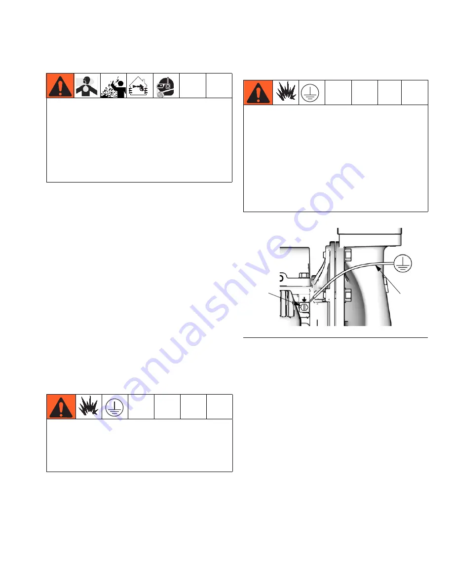
Grounding
Pump:
See F
IG
. 1. Loosen the grounding
screw (GS). Insert one end of a 12 ga.
minimum ground wire (R) behind the
grounding screw and tighten the screw
securely. Connect the clamp end of the ground
wire to a true earth ground. A ground wire and
clamp, Part 238909, is available from Graco.
Air and fluid hoses:
Use only grounded
hoses
with a maximum of 500 ft (150 m) com-
bined hose length to ensure grounding conti-
nuity.
Air compressor:
Follow manufacturer’s
recommendations.
Fluid supply container:
Follow local code.
Solvent pails used when flushing:
Follow
local code. Use only conductive metal pails,
placed on a grounded surface. Do not place
the pail on a nonconductive surface, such as
paper or cardboard, which interrupts ground-
ing continuity.
•
The pump exhaust air may contain con-
taminants. Ventilate to a remote area. See
Air Exhaust Ventilation
on page
11.
•
Never move or lift a pump under pressure.
If dropped, the fluid section may rupture.
Always follow the
Pressure Relief Proce-
dure
on page
16
before moving or lifting
the pump.
The equipment must be grounded to reduce
the risk of static sparking. Static sparking can
cause fumes to ignite or explode. Grounding
provides an escape wire for the electric
current.
Polypropylene and PVDF:
Only aluminum,
conductive polypropylene, hastelloy, and
stainless steel pumps have a ground screw.
Standard polypropylene and PVDF pumps
are
not
conductive.
Never
use a non-con-
ductive polypropylene or PVDF pump with
non-conductive flammable fluids. Follow your
local fire codes. When pumping conductive
flammable fluids,
always
ground the entire
fluid system as described.
F
IG
. 1. Grounding screw and wire
ti12214a
GS
R


