background image

Operation 

40

3A2175Z

Pressure Relief Procedure

1. Shut off feed pumps and agitator, if used.

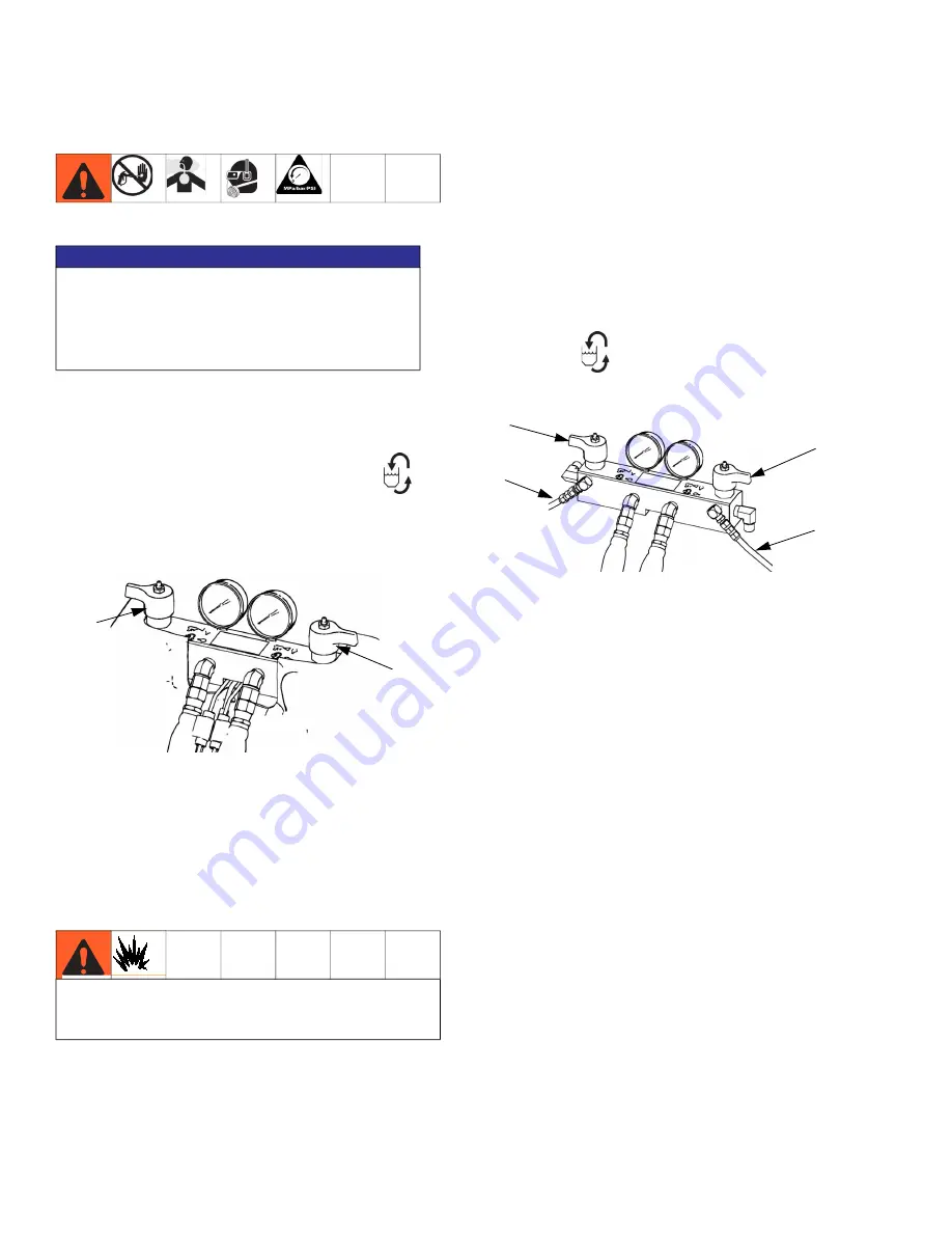
2. Turn PRESSURE RELIEF/DISPENSE valves (SA, 

SB) to PRESSURE RELIEF/CIRCULATION 

Route fluid to waste containers or supply tanks. 

Ensure gauges drop to 0.

3.

For models with an dispense valve with a safety 

lock,

 engage gun safety lock.

4. Relieve pressure in dispense valve. See dispense 

valve manual.

Flushing

• Flush out old fluid with new fluid, or flush out old 

fluid with a compatible solvent before introducing 

new fluid.

• Use the lowest possible pressure when flushing.

• All fluid components are compatible with common 

solvents. Use only moisture-free solvents. See 

Accessories

 on page 136 for list of wetted compo

-

nents to verify compatibility of solvent with wetted 

materials. See solvent manufacturers information 

for material compatibility.

• To flush feed hoses, pumps, and heaters separately 

from heated hoses, set PRESSURE RELIEF/DIS

-

PENSE valves (SA, SB) to PRESSURE RELIEF/CIR

-

CULATION 

. Flush through bleed lines (N).

• To flush entire system, circulate through gun fluid 

manifold (with manifold removed from gun).

• To prevent moisture from reacting with isocyanate, 

always leave the system dry or filled with a mois

-

ture-free plasticizer or oil. Do not use water. See 

Important Two-Component Material Information


on page 14.

Solvent pails used when flushing

: follow your local 

code. Use only metal pails, which are conductive, 

placed on a grounded surface. Do not place pail on 

a nonconductive surface, such as paper or card

-

board, which interrupts grounding continuity.

To maintain grounding continuity when flushing or 

relieving pressure,

 hold a metal part of dispense 

gun firmly to the side of a grounded 

metal

 pail, then 

trigger gun.

NOTICE

The fittings on the pressure relief hoses are zinc 

plated carbon steel. The hoses are cured with sul

-

fur. Check your materials for compatibility with zinc 

plating and sulfur before reusing any material that 

passed through them, as it may inhibit curing.

Flush equipment only in a well-ventilated area. Do not 

dispense flammable fluids. Do not turn on heaters 

while flushing with flammable solvents.

ti9879a1

SA

SB

SA

SB

ti9880a1

N

N

Summary of Contents for HFRL

Page 1: ...ng laminates and silicones For professional use only Not approved for use in explosive atmospheres or hazardous locations See page 4 for model information and maximum working pressure Important Safety...

Page 2: ...Advanced Display Module ADM Operation 57 Appendix A ADM Icons Overview 58 Setup Screen Icons 58 Run Screen Icons 59 Appendix B ADM Setup Screens Overview 60 Appendix C ADM Run Screens Overview 77 App...

Page 3: ...structions Parts 3A0020 HFR Hydraulic Actuator Instructions Parts Feed System Manuals for HFRL Systems 3A0235 Feed Supply Kits Instructions Parts Dispense Valve Manuals 312185 MD2 Valve Instructions P...

Page 4: ...tested under application conditions Dispense rate in excess of max flow and pressure may result in an elevated temperature of the hydraulic system resulting in a thermal shutdown T4H1 Other system mod...

Page 5: ...n 230 1 1 67 1 50 30 Carbon Steel HFRL11 HFR for Lamination 230 1 1 86 1 160 86 Carbon Steel HFRL12 HFR for Lamination 230 1 2 00 1 50 25 Carbon Steel HFRL13 HFR for Lamination 230 1 2 15 1 86 40 Carb...

Page 6: ...d intermittent use Lower cycle rates may be possible but should be tested under application conditions Flow rates are established 2500 psi 17 MPa 172 bar Dispense rate in excess of max flow and pressu...

Page 7: ...1 Stainless Steel 5 5 Feed HFRS21 HFR for Silicone 230 1 5 33 1 Car bon Steel 55 55 Feed HFRS22 HFR for Silicone 230 1 5 33 1 Car bon Steel 55 5 Feed HFRS23 HFR for Silicone 230 1 5 33 1 Car bon Stee...

Page 8: ...Steel 5 5 Feed HFRS66 HFR for Silicone 400 3 2 1 Stainless Steel 55 55 Feed Part Num ber Description HFRS67 HFR for Silicone 400 3 2 1 Stainless Steel 55 5 Feed HFRS68 HFR for Silicone 400 3 2 1 Stain...

Page 9: ...mps HFRS94 HFR for Silicone 230 1 1 1 Carbon Steel 5 5 Feed 40 40 pumps HFRS95 HFR for Silicone 400 3 1 1 Carbon Steel 55 55 Feed 40 40 pumps HFRS96 HFR for Silicone 400 3 1 1 Carbon Steel 5 5 Feed 40...

Page 10: ...f it according to applicable guidelines Always wear chemically impermeable gloves when spraying dispensing or cleaning equipment PERSONAL PROTECTIVE EQUIPMENT You must wear appropriate protective equi...

Page 11: ...in the work area See Grounding instructions Use only grounded hoses Hold gun firmly to side of grounded pail when triggering into pail If there is static sparking or you feel a shock stop operation im...

Page 12: ...Relief Procedure when equipment is not in use Check equipment daily Repair or replace worn or damaged parts immediately with genuine man ufacturer s replacement parts only Do not alter or modify equip...

Page 13: ...Warnings 3A2175Z 13...

Page 14: ...se supplied with your system Never use reclaimed solvents which may contain moisture Always keep solvent containers closed when not in use Never use solvent on one side if it has been con taminated fr...

Page 15: ...component materials Be aware that when standing in front of the manifold on proportioner Component A Red is on the left side Component B Blue is on the right side For all machines The A Red side is in...

Page 16: ...B Power Module C B Blue Pump D A Red Pump E Outlet Module F B Hose Kit G A Hose Kit H Dispense Gun J Orifice Block K Orifice 1 4 L Supply Unit B Side M Supply Unit A Side N Supply Hose P Inlet Regula...

Page 17: ...inate AB Power Module AC B Blue Pump AD A Red Pump AE Outlet Module AF B Hose Kit AG A Hose Kit AH Dispense Gun AJ Orifice Block AK Orifice 1 4 AL Inlet Assembly AM Grease Reservoir Bottle not shown F...

Page 18: ...Connection from feed to gun or mix head BN Component B Blue Hose Connection from feed to gun or mix head BP Hydraulic Power Pack Assembly BR Hydraulic Tank BS Grease Reservoir Bottle Included on all...

Page 19: ...nt Identification shown with shrouds removed ti9880a1 Fluid Manifold FM Detail BU CC CB Rear View 24C352_313998_4e HFRL Material Inlet 250 psi Max HFRS Material Inlet 3000 psi Max ti18211a ti18212a BJ...

Page 20: ...n Circuit Breakers The circuit breakers are located on the panel assembly mounted directly behind the disconnect switch panel on the right side of the enclosure For more information about items on the...

Page 21: ...Accessories on page 136 for specifications DB Electric Motor DC Dipstick not shown located at rear left of hydraulic tank DD Hydraulic Housing DE Directional Valve DF Motor Control Module see page 22...

Page 22: ...up The Motor Control Module uses an 8 position selector switch to set the system maximum working pressure NOTICE If the Motor Control Module is replaced the selec tor switch must be set prior to initi...

Page 23: ...ensor Dispense Valve Solenoid and Footswitch 3 Oil Temperature Sensor 5 Electric Motor Temperature Sensor 6 LVDT 7 Three way Splitter to Hydraulic Directional Valve Oil Overtemperature Switch 8 Pressu...

Page 24: ...Sys tem Status Indicator EB Condi tions on page 25 for details EC Stop Stop all system processes Is not a safety or emergency stop ED Soft Keys Defined by application using ADM EE Cancel Cancel a sele...

Page 25: ...atus LEDs EP Accessory Cable Connections ER Token Access Cover ES Battery Access Cover System Status Indicator EB Conditions Green Solid Run Mode System On Green Flashing Setup Mode System On Yellow S...

Page 26: ...ormational components of each screen For details regarding the user interface display see Advanced Display Module ADM Operation page 57 FIG 9 Main Display Components Current date and time Current scre...

Page 27: ...entification 3A2175Z 27 Fluid Control Module FCM Key FA Fluid Control Module FB Base FC Module Connection Screws FD Access Cover FE Module Status LEDs FF CAN Connectors FIG 10 ti12337a1 ti12336a1 FA E...

Page 28: ...he EP Gun and MD2 Valve are examples of solenoid controlled dispense valves which are controlled by the HFR The user does NOT directly control the dispense valve solenoid In this configuration the use...

Page 29: ...alve solenoid needs installed to control the dispense valve Dispense valve configuration 2 a Graco 24C757 can be installed onto the side of the HFR After it is mounted connect the valve solenoid to th...

Page 30: ...ase L1 L2 L3 N GND Use 5 32 or 4 mm hex allen wrench to connect the two or three power leads to L1 L2 and L3 as applicable Connect green to ground GND Electrical Cord Wires by Model 230V 1phase L1 L2...

Page 31: ...age level stored on the capacitive bus in power conversion equipment Reading should not regularly exceed approximately 400VDC to avoid tripping the 420VDC alarm level in the Motor Control Module If po...

Page 32: ...NOTE A minimum feed pressure of 50 psi 0 35 MPa 3 5 bar is required at both feed inlet pressure gauges FP Maintain A Red and B Blue feed pressures within 10 of each other b Ensure A Red and B Blue inl...

Page 33: ...ifold to adapt to the dispense hose fitting 8 Assemble MD2 adapters a Install orifice valve blocks to material inlets b Install appropriate hose adapters into orifice valve blocks Do not install shuto...

Page 34: ...tal pails which are con ductive placed on a grounded surface Do not place pail on a nonconductive surface such as paper or cardboard which interrupts grounding continuity e To maintain grounding conti...

Page 35: ...display and adjust as nec essary i If equipped check fluid pressure gauges GA GB to ensure proper pressure balance If imbalanced reduce pressure of higher compo nent by slightly turning PRESSURE RELI...

Page 36: ...signal cable 120955 provided with the machine and making contact between the brown 1 and blue 3 wires The black wire is connected to pin 4 and is not used for customer connection For reference see th...

Page 37: ...ves SA SB to DISPENSE g Start feed pumps h Open fluid inlet valves FV if equipped Check for leaks i Prime material regulators with fluid Refer to Adjusting Material Inlet Pressure Using the Material R...

Page 38: ...the left most extreme position e After the pump stops moving press the con tinue button to go on to the next step in the calibration process or the page back button to return to the main Calibration s...

Page 39: ...e to the pressure imbalance field d Type the desired pressure imbalance setting then press Enter Shutdown 1 Park pumps a From the Home screen press and select Standby mode b Press Material will dispen...

Page 40: ...Flush through bleed lines N To flush entire system circulate through gun fluid manifold with manifold removed from gun To prevent moisture from reacting with isocyanate always leave the system dry or...

Page 41: ...ding on the material viscosity and flow rate 10 Once material is flowing from the bleed hose slowly decrease pressure on the material regulator until flow stops 11 Gradually increase pressure to the m...

Page 42: ...desired flow rate with no orifice valves installed to evaluate the dis pense pressures generated for each material NOTE Appropriate orifice valve selection is essentially done by trial The following...

Page 43: ...s 0 016 1 0 1 6 2 3 3 1 3 8 4 8 5 9 6 9 8 6 10 6 11 8 14 1 15 5 17 5 20 8 28 9 0 020 1 6 1 0 1 4 2 0 2 4 3 1 3 8 4 4 5 5 6 8 7 6 9 0 9 9 11 2 13 3 18 5 0 024 2 3 1 4 1 0 1 4 1 7 2 1 2 6 3 1 3 8 4 7 5...

Page 44: ...As Needed If equipped inspect IsoGuard Select fluid level and condition refill or replace as needed page 50 Daily Check hydraulic fluid level Weekly Grease circulation valves with Fusion grease 11777...

Page 45: ...ry according to local codes 5 Replace rear access panel 6 Connect the power to the ADM and reset the clock through Advanced Screen 1 Refer to Appendix B ADM Setup Screens Overview for more detail Clea...

Page 46: ...oftware On system software version 1 12 001 February 2020 and later a single 16H821 programming token can be inserted into the ADM to re program most of the soft ware modules after power is cycled To...

Page 47: ...e screen below 4 Select and check the Use ADM to Program Token checkbox option select out of the current screen and navigate one screen left Go to the Advanced setup screen pages 5 Navigate to the Adv...

Page 48: ...ck valves Inspect the screens daily as part of the startup routine and clean as required The standard strainer is 20 mesh Use clean chemicals and follow proper storage trans fer and operating procedur...

Page 49: ...hardened remove the hard ened materials or grease Shorten the intervals between greasing the pump If the grease remains clear and free of material inter vals between greasing the pump can be increase...

Page 50: ...reverse threads 4 Remove needle from orifice Thoroughly inspect all o rings and replace if necessary 5 If necessary use drill bit that is the same size as the orifice to drill out the orifice Orifice...

Page 51: ...eral Display Module completely dark No Power Verify AC Power switch is ON Thrown Breaker Check Machines Breakers and Reset Loose Connection Tighten 5 pin cable on Advanced Display Module Bad Display M...

Page 52: ...nt Pump cavitation Feed pump pressure is too low Adjust pressure to maintain 100 psi 0 7 MPa 7 bar minimum Pump output low Obstructed fluid hose or gun fluid hose ID too small Open clear use hose with...

Page 53: ...CM CS ti12363a1 Module Status LED Signal Description Green on System is powered up Yellow on Communication in progress Red solid ADM hardware failure Red flashing Uploading software Module Status LED...

Page 54: ...LED Status Signal Module Status LED Signal Description Green on System is powered up Yellow on Internal communication in progress Red solid MCM hardware failure Replace MCM Red flashing fast Uploading...

Page 55: ...ermanently damage hard ware The chart below shows the permissible magni tude and duration of temporary over voltage events Consult a qualified electrician if there are any concerns about the available...

Page 56: ...LED Signal Diagnosis Green on System is powered up Yellow Internal communication in progress Red solid FCM hardware failure Replace FCM Red flashing fast Uploading software Red flashing slow Token er...

Page 57: ...m the following tasks to fully setup your system 1 Set general system settings See Advanced Screen 1 page 71 2 Set units of measure See Advanced Screen 2 page 71 3 Enable disable system features See A...

Page 58: ...o next step in calibration procedure On Main Calibration screen Calibrate Weight Dispense or Enter Specific Gravity Information On Flow Meter Calibration screen Use Dispensed Material Weight to Calibr...

Page 59: ...o matic Circulation Options Press a second time to exit Circula tion and return to Dispense mode Sets machine to low pressure Sets machine to high pressure Current and setpoint temperature for primary...

Page 60: ...ADM keypad to enter the password then press From the Setup screens press to access the Run screens For Run screens information see Appendix C ADM Run Screens Overview on page 77 FIG 23 shows the flow...

Page 61: ...desired value 2 Type the new value then press the Enter button to accept the new value 3 If desired press to quickly enter the same value for the rate and time volume weight 4 Repeat step 2 as require...

Page 62: ...for 75 cc 1 Dispense 5 shots into 5 separate containers 2 Measure the dispensed amount and record the data 3 Calculate the average of the 5 shots Example 3 72 5cc 4 Use the following formula to calcu...

Page 63: ...e available for selection in a sequence Blank positions containing a 0 in sequence will be skipped by the HFR sequence logic For example sequence Y in the screen shown below will dispense shot numbers...

Page 64: ...Learn Mode Press to go to the Calibration Screen Learn Mode screen Press to erase the motor control database in the motor control module Calibration Screen Learn Mode This screen allows the user to ca...

Page 65: ...erify the correct dis pense valve is selected on System Screen 2 System Screen 2 This screen allows the user to set the Gel Timer proper ties and set which items are installed on the machine When enab...

Page 66: ...B Blue sides of the machine The labels set for the A Red and B Blue sides of the machine are displayed throughout the screens Labels are limited to five characters To edit a label 1 Press 2 To edit t...

Page 67: ...ON time when air is applied off time air valve is closed and delay the start of air application at the start of the dispense When the HFR is NOT dispensing no air is applied to the dynamic mixer The b...

Page 68: ...ut installing level sensors see Related Manuals on page 3 The user may select from the following refill settings Disabled Monitor Manual Auto Top Off Auto Full Volume NOTE Use the Disabled setting if...

Page 69: ...are set to installed the system will default to the Auto Top Off refill setting and operate as follows The low level sensor will generate a low level alarm The high level sensor will generate a high...

Page 70: ...eriodically Press the Enter Screen button and adjust the on and off durations as desired When the system is in Night Mode and in an On cycle the system will circulate in low pressure The installed con...

Page 71: ...71 Advanced Screen 1 This screen allows the user to set the language date format current date time setup screens password screen saver delay and turn on or off silent mode Advanced Screen 2 This scree...

Page 72: ...the most consistent material amounts but will provide inconsistent dispense delays after a dispense request is issued Operator Mode Cavitation Alarm Check this box to enable cavitation alarms in Opera...

Page 73: ...ak error if more than two automatic fill operations occur and no dispenses have occurred during that time Use ADM to Program Token If the function is enabled by an X in the check box the user will be...

Page 74: ...un screen Controlling Stall Pump Use this feature to select the controlling pump constant pressure mode or stall pump at the end of constant flow or constant pressure non circulation dispense Four sel...

Page 75: ...ontrol options Disable Pressure Imbalance Alarms Checking this option will disable the generation of pressure imbalance alarms resulting from an excessive pres sure difference between the HFR Blue and...

Page 76: ...ar Lens options are currently available using the drop down selection Blue Token Reader This feature is represented by the blue token graphic shown next to the bottom left softkey graphic To enable th...

Page 77: ...errors If tanks are installed in the system the fill level is shown on each tank To select an operating mode press the Select Mode button repeatedly until the desired mode is shown then press the Ente...

Page 78: ...ect one of 100 pre defined shot numbers See Shots Screen on page 61 for information about editing shot definitions To use a predefined shot 1 Enter shot mode 2 Press and use the numeric keypad to ente...

Page 79: ...Mode This mode allows users to set a pressure or flow rate to dispense material without using predefined shot infor mation Pressure or flow rate availability is dependent on the Control Mode selection...

Page 80: ...culation on off cycle begins automatically upon entering Night Mode See Conditioning Screen 3 on page 70 Home Screen Disabled Mode When this mode is selected the machine will not be able to dispense o...

Page 81: ...ndividually or all at once The grey circles indicate that a zone is off and green circles indicate that a zone is on When a zone is on it is actively controlling temperature To turn a single zone on o...

Page 82: ...r is disabled for dispensing an ECD0 R Mixer Motor Disabled for Dispense event will be recorded on the USB logs and the event run screen Likewise if nucleation is disabled during a dispense a ECF0 R M...

Page 83: ...d next to the vol ume weight indicator icons To erase a batch counter press the Enter Screen but ton and navigate to the field to be erased Press the Erase Single button to erase that data point Alter...

Page 84: ...6 Red Blanket Overcurrent An over current was detected on the output Alarm Bad heaters Measure resistance of heater A4B5 Blue Blanket Overcurrent A4A3 Red Inline Overcurrent A4B1 Blue Inline Overcurre...

Page 85: ...dition A8B5 No Blue Blanket Current A8A3 No Red Inline Current A8B1 No Blue Inline Current A8A2 No Red Hose Current A8B4 No Blue Hose Current Low power Measure voltage across input terminals on power...

Page 86: ...tex FCM3 is disconnected FCM3 failure Reconnect ensure cable Verify proper LED indications on Voltex FCM3 CUCN Gateway Heartbeat Error Heartbeat Error Alarm PLC is not maintaining heartbeat Ensure PLC...

Page 87: ...d Clear or replace hose as necessary Dispense valve failed to open Check to make sure the dispense valve is properly configured and connected to the MCM DR6A Check Flow Meter Red Flow Meter has caused...

Page 88: ...is properly connected to the MCM and that the wire has not been damaged Bad level sensor Replace sensor Leak in hydraulic driver Inspect hydraulic driver end seals and early leak detection tubing Repl...

Page 89: ...the requested pressure is within the max operating pressure which can be found on the setup screen System 1 Orifices blocked Clear blockage Hose blocked Clear blockage or replace hose as necessary Di...

Page 90: ...y check circuit breaker for a tripped condition T1B5 Blue Tank Low Fluid Temp T1A3 Red Inline Low Fluid Temp T1B1 Blue Inline Low Fluid Temp T1A2 Red Hose Low Fluid Temp T1B4 Blue Hose Low Fluid Temp...

Page 91: ...age is possible so the Motor Control Module is limiting the output to a safe level Deviation No power to fan Check cord to make sure fan has power Debris is fan or fan grill Clear debris from fan fan...

Page 92: ...draulic oil is at a temperature where performance is impacted significantly and has resulted in a system shutdown Alarm No Power to Fan Check cord to make sure fan has power Debris in fan or fan grill...

Page 93: ...d heater s Measure resistance of heater s T8A7 No Cooling Red Chiller No temperature decline Alarm Tripped circuit breaker Visually check circuit breaker for a tripped condition T8B8 No Cooling Blue C...

Page 94: ...Hose Overvoltage V4B4 Blue Hose Overvoltage V4A7 Red Chiller Overvoltage V4B8 Blue Chiller Overvoltage V4H0 MotorControl Overvoltage The voltage to the MCM has reached an unsafe level and has been sh...

Page 95: ...e The directional valve will need to be replaced Hydraulic power pack failure The hydraulic power pack will need repair Defective encoder Replace encoder Motor no longer coupled to hydraulic pump Rese...

Page 96: ...ctly setup On the ADM go into the setup screens System and ensure that all pages have properly defined values Shot incorrectly defined Redefine shot with control parameters within the limits of the sy...

Page 97: ...average for point one of the three point calibration was erased RENC5 Cal Point 2 Weight Erased The running average for point two of the three point calibration was erased REND0 Ratio Check Dispense A...

Page 98: ...d operator modes The second option is the Erase icon which will reset the last download date to a time where all logs can be downloaded 10 25 18 This will allow the user to download all the USB log en...

Page 99: ...created The number at the end of the folder name is incremented each time a stick drive is inserted and data is down loaded or uploaded In each DATAxxxx folder there is two log files They are formatte...

Page 100: ...Appendix F USB Operation 100 3A2175Z Example LOG01 File The LOG01 file is the Errors and Events log file Example LOG02 File The LOG02 file is the Shot Data Log file...

Page 101: ...software is updating the system a pop up box will appear to inform the user of the update and the system will lock Once the update is complete the ADM will tell the user to cycle power to apply the u...

Page 102: ...must remain DISPTEXT TXT 6 Copy the edited DISPTEXT TXT file into the UPLOAD folder 7 Remove the USB stick drive from the computer and install it into the ADM USB port The software will automatically...

Page 103: ...3A2175Z 103 Example SETTINGS TXT File Example DISPTEXT TXT File NOTICE The user should never attempt to modify the SET TINGS TXT file in any way Graco is not responsible for damages caused by an impro...

Page 104: ...ecause of this the temperature reading dis played on the HFR ADM module may be affected by the heating element of the zone especially if the machine is idle or stalled to pressure For these situations...

Page 105: ...le on HFR systems with logic versions 1 10 001 or later The fully Automatic feature is available on logic versions 1 11 001 or later Manual Recirculation Feature This version uses the Graco circulatio...

Page 106: ...HFR Semi and Fully Automatic Circulation Kit ti19957a Apply pipe sealant to all male threads as needed prior to assembly Torque to 8 ft lb 11 N m 2 4 HFR Circulation Kit 24N486 24N487 215 216 201 202...

Page 107: ...r temp cond 1 1 1 206 158683 FITTING elbow 90 deg 1 1 207 100206 BUSHING pipe 1 1 208 6310 200 ADAPTER jic 05 x 1 2 npt m ms 1 94 0653 99 ADAPTER jic06 x 1 2 npt mm ms 3k 1 209 262175 HOSE A 10 ft 3 m...

Page 108: ...108 3A2175Z FIG 29 HFR Semi and Fully Automatic Valve Kit Apply pipe sealant to all male threads prior to assembly 1 Solenoid Valve Manual 24N990 316 312 302 312 305 306 315 313 304 303 307 301 309 30...

Page 109: ...1022 FITTING elbow male 1 4 npt 2 305 121021 MUFFLER 1 4 npt 2 306 123395 HARNESS pwr valve tank 1 307 112698 ELBOW male swivel 4 308 115968 SCREW cap socket head 3 309 GC2107 WASHER lock spring 8 3 3...

Page 110: ...ate in flow mode regardless of whether the user is dis pensing out of the valve in constant pressure or flow The user can now circulate the material by pressing the dispense key pressing the footswitc...

Page 111: ...valve in flow mode The user can cir culate the materials at a flow rate different than the dis pense rate If dispensing in constant pressure mode the pumps will stop momentarily during the transition...

Page 112: ...elect the mode at this time then select the correct sequence and position for dispense Start the circulation process by pressing the footswitch tap once or twice if in shot mode and the 2X Trigger for...

Page 113: ...ssurize Before Opening DV feature was added to the Auto Circulate Between Dispenses option as indicated in the Advanced Screen 6 shown below The new feature is intended to pressurize the two materials...

Page 114: ...pability HFR systems with the HFR Recirculation Valves Installed feature a night mode selection capability The user can select Night Mode which allows the pumps and optional heating zones to be turned...

Page 115: ...Amount o of Req t Amount Nominal Size g Tol Max Tol Min USL LSL Std Dev Mean Maximum Minimum Cp Cpkl Cpku 0 5 10 15 20 25 30 0 5 10 15 20 25 30 35 Shot Weight Max Min HFR Pump Types HFR Con gura on Mi...

Page 116: ...1704 Furthermore this newer map will support some of the newer features provided by the HFR product such as a Dynamic Mixer option ability to change recirculation flow rates and ability to request a d...

Page 117: ...8 See Available Internal Data page 120 for details on FieldBus pinout setup 9 Perform the setup to configure the FieldBus Setup Gateway Screens The gateway screens are used to configure the fieldbus...

Page 118: ...have a DeviceNet FieldBus CGM installed This screen enables the user to set the device address and baud rate and to view the hardware revision system serial number and data map identification informat...

Page 119: ...screens are shown only if you have a PROFINET FieldBus CGM installed Screen 1 This screen enables the user to set the IP address DHCP settings subnet mask gateway and DNS infor mation See FIG 57 Scre...

Page 120: ...ts 4 8 9 I64 I79 Current Dispense Duration which counts up starting from 0 in 0 01 second units 5 10 13 I80 I111 Amount for current Dispense In 0 01 CC or 0 01 Gram units starting from 0 6 14 17 I112...

Page 121: ...t 2 4 4 5 O32 Turn On System Request O33 PLC Robot CGM Control Request O34 Heart Beat from PLC O35 ADM Lock Out Request O36 Red Tank Manual Fill Request O37 Blue Tank Manual Fill Request O38 Turn ON T...

Page 122: ...screen provides graphical representations of the data provided to the controlling logic The bit data below is on high when the circle graphic is green and off low when the graphic is Grey See New Fiel...

Page 123: ...ability for 26 different sequences A Z each with up to 20 positions The sequences can be defined using the sequences screens in the ADM See FIG 61 Positions in possible 20 positions can be skipped and...

Page 124: ...ng the system startup control bit after the NVH system has been idle for some time System is Ready for Dispense Request I175 This informs the controlling logic it is OK to request a dispense If set th...

Page 125: ...he HFR system to data exchange interface output data element location output byte locations 22 25 O176 O207 2 Write to the data exchange interface data pointer command location on the map output bytes...

Page 126: ...C0 units Write 12 Read 13 Red Material Chiller Temperature Set point temperature Set or Get Set Point temperature in 0 1 C0 units Write 14 Read 15 Blue Material Chiller Temperature Set Point temperat...

Page 127: ...te 1 Material is below Low Level sensor 2 Material between Low and High Level 2nd sensors 3 Tank Full at 2nd sensor or above 7 Material at or above top sensor Report xxx High Level in bit 2 feature ON...

Page 128: ...ror provided If this register is assigned one of the read configu rable data registers see next items in table if more than 1 error is present the HFR will present all the active error numbers at appr...

Page 129: ...ler Write 188 Read 200 Mixed Material in Current or Last Dispense Sum of Blue and Red Materials Dispensed In 0 01 CC or 0 01 Gram units Read 202 Blue Material in Current or Last Dispense In 0 01 CC or...

Page 130: ...rite If sending a Turn On Request the system should be idle and Not dispensing Write 244 Read 251 Recirculation Flow Rate Set Point Set Write or get read the recirculation flow rate set point in in 0...

Page 131: ...A Blue Motor Over Current 7 7 A4N1 A Blue Motor Over Current 8 8 A4M1 A Blue Motor Over Current 9 9 A9C1 A Blue Motor Over Current 10 10 T4C1 A Blue MCM High Temp 11 11 V4H0 A Blue MCM Overvoltage 12...

Page 132: ...1 92 A4B8 A Blue Chiller Overcurrent 62 93 A7A6 A Red Blanket Control Fault 63 94 A7B5 A Blue Blanket Control Fault Item Error Number Code Level Description 64 95 A7A3 A Red Inline Control Fault 65 96...

Page 133: ...1B1 D Blue Inline Low Fluid Temp Item Error Number Code Level Description 108 147 T1A2 D Red Hose Low Fluid Temp 109 148 T1B4 D Blue Hose Low Fluid Temp 110 149 T1A7 D Red Chiller Low Fluid Temp 111 1...

Page 134: ...lue Tank Con Fault Unexpected Relay I 156 195 WMC3 A Red Inline Con Fault Unexpected Relay I 157 196 WMC1 A Blue Inline Con Fault Unexpected Relay I Item Error Number Code Level Description 158 197 WM...

Page 135: ...m Error Blue Chiller 208 252 CACN A Comm Error Field Bus Item Error Number Code Level Description 209 253 CUCN A Field Bus Heartbeat Failure 210 254 CACP A Comm Error Discrete I O 211 255 CACR A Comm...

Page 136: ...machine See HFR Discrete Gateway Module manual 3A1149 for more information Secondary Supply Pump to Create a Tandem Unit HFRS Equipment Only Part No Description 24M154 IsoGuard Select Assembly with 3...

Page 137: ...Accessories 3A2175Z 137...

Page 138: ...uid Working Pressure HFRL Models 2000 psi 14 MPa 138 bar HFRS Models 3000 psi 21MPa 207 bar See Models starting on page 4 for specific flow rate and pressure information Maximum Fluid Temperature 120...

Page 139: ...cations Input Line Voltage 0 264 Vac line to line Input Line Phasing Single or Three Phase Input Line Frequency 50 60 Hz Input Current per Phase 25A three phase 50A single phase Maximum Branch Circuit...

Page 140: ...Motor Control Module Technical Data 140 3A2175Z Dimensions ti18219a 58 1 in 1476 mm 51 8 in 1316 mm 37 2 in 945 mm 24 in 610 mm 15 in 381 mm 4 5 8 diameter anchor locations 5 in 127 mm...

Page 141: ...California Proposition 65 3A2175Z 141 California Proposition 65 CALIFORNIA RESIDENTS WARNING Cancer and reproductive harm www P65warnings ca gov...

Page 142: ...ade at a reasonable charge which charges may include the costs of parts labor and transportation THIS WARRANTY IS EXCLUSIVE AND IS IN LIEU OF ANY OTHER WARRANTIES EXPRESS OR IMPLIED INCLUDING BUT NOT...

Reviews: